The latest revision of CISPR 25 is looking into various types of Artificial Networks used in today's automotive EMC.
1. Artificial Network (AN): used for LV power supplies;
2. High Voltage Artificial Network (HV-AN): used for high voltage d.c. power supplies;
3. Direct Current charging Artificial Network (DC-charging-AN): used for d.c. power supplies;
4. Artificial Mains Network (AMN): used for a.c. power mains;
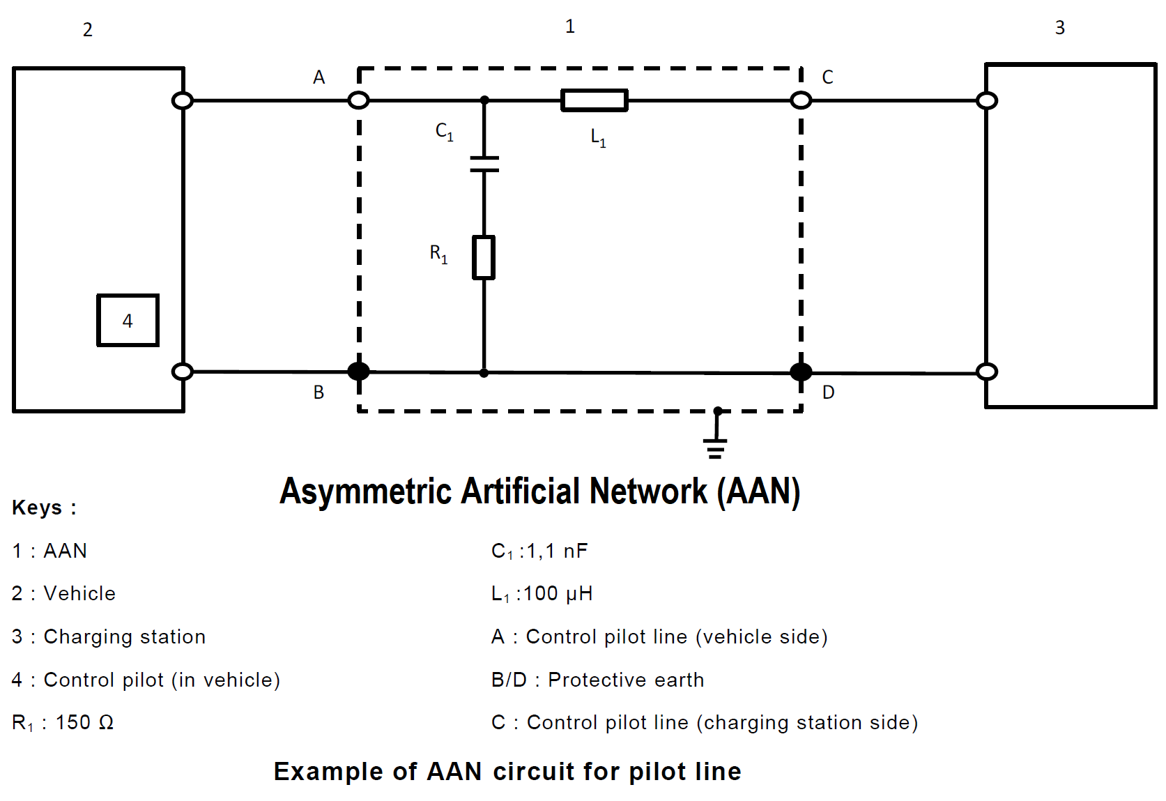
5. Asymmetric Artificial Network (AAN): used for signal/control port lines and/or wired network port lines.
1. Artificial Network (AN)
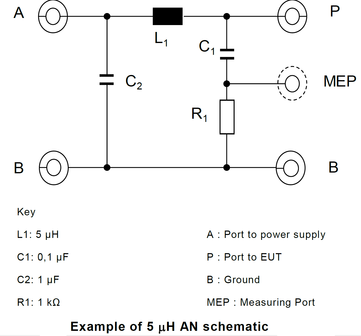
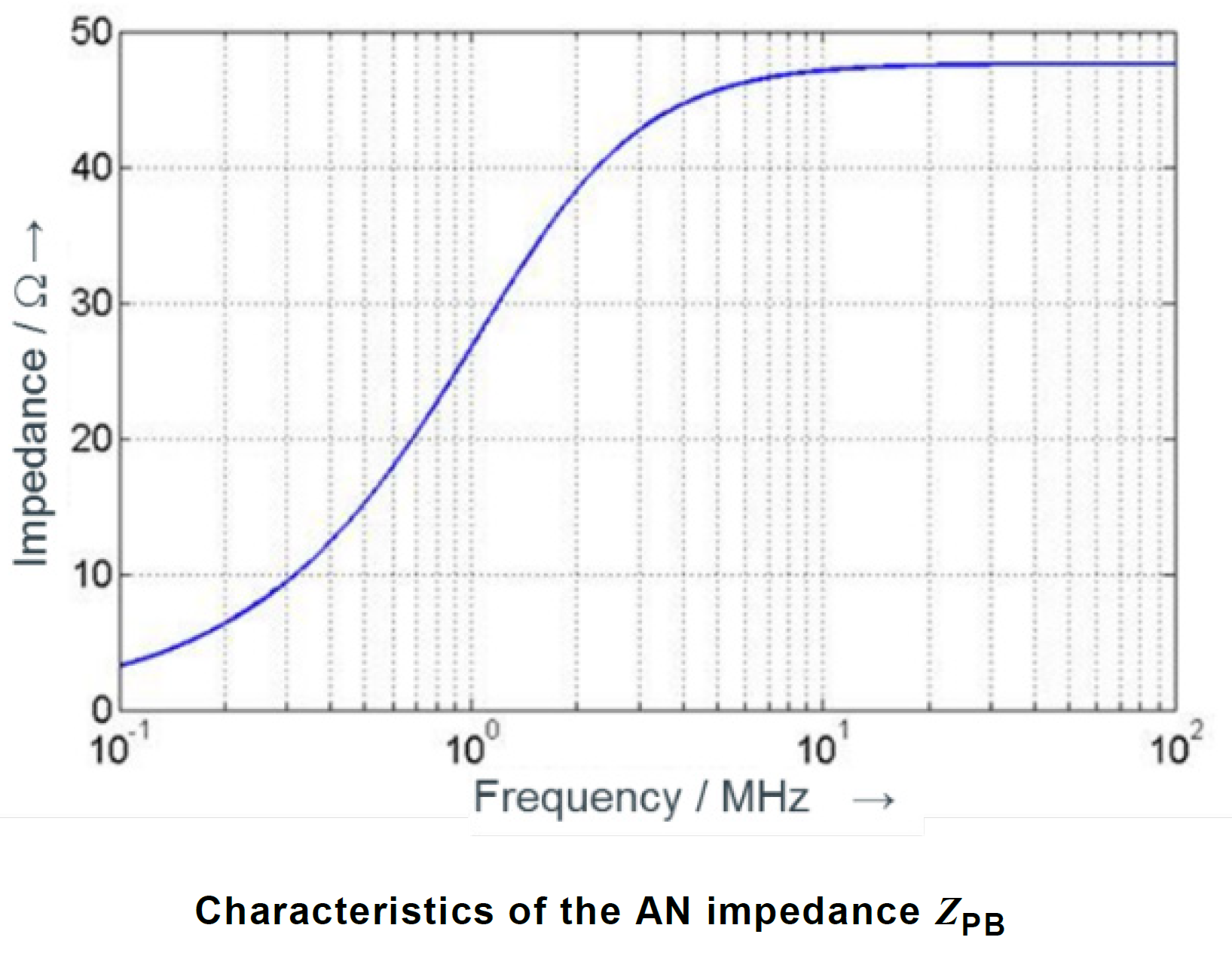
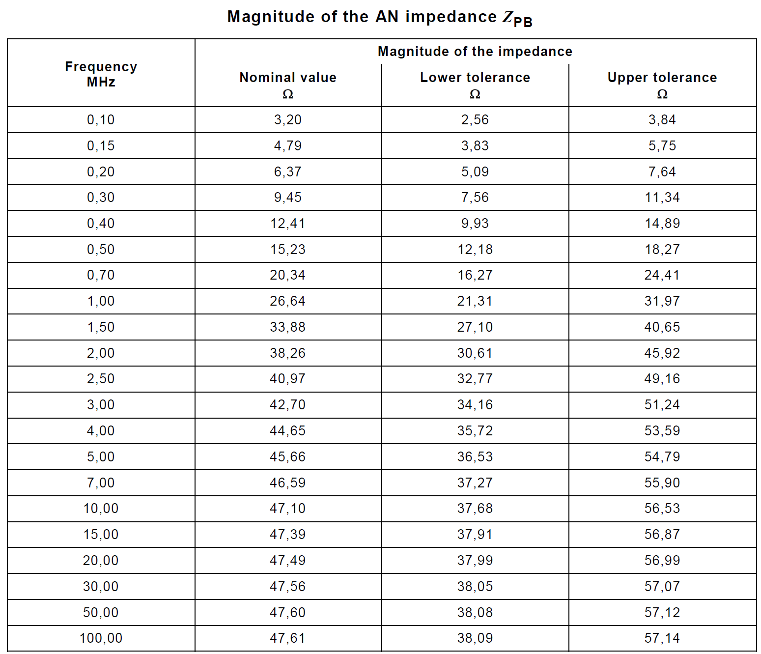
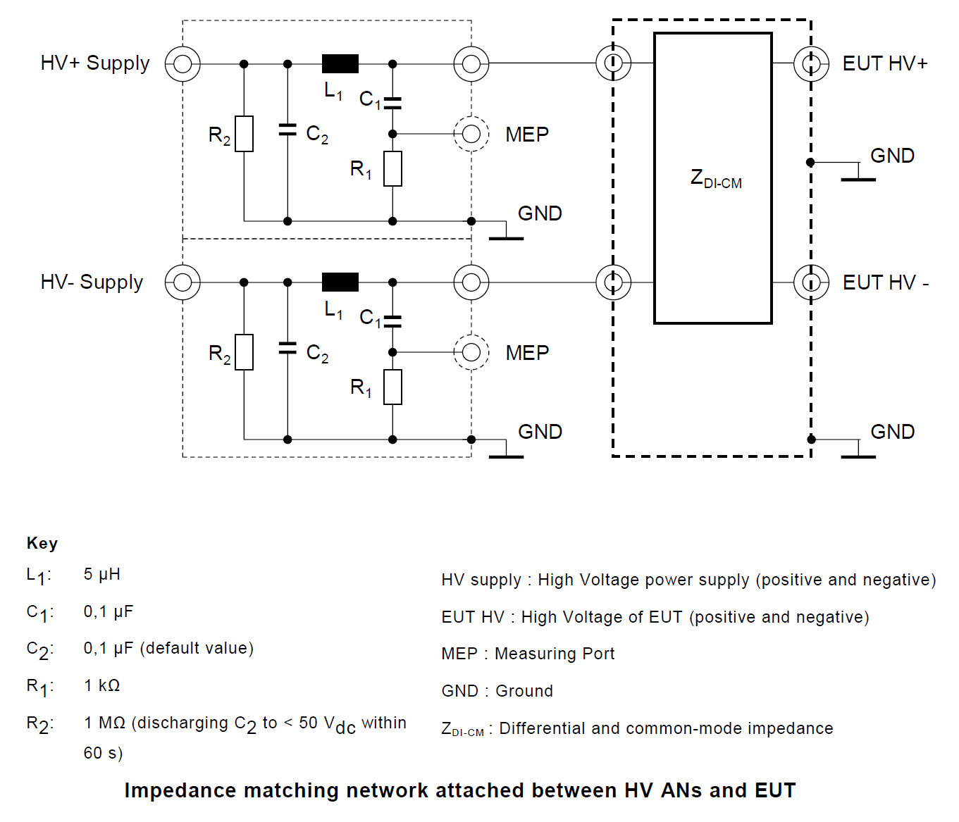
Measurement ports of HV-AN(s) must be terminated with a 50 Ω load. The HV-AN impedance ZPB (tolerance ± 20 %) in the measurement frequency range of 0.1 MHz to 100 MHz. This table above shows the nominal impedance and upper/lower tolerances in tabular form. It is measured between the EUT HV and ground terminals with a 50 Ω load on the measurement port and with the supply line HV and ground terminals short circuited.
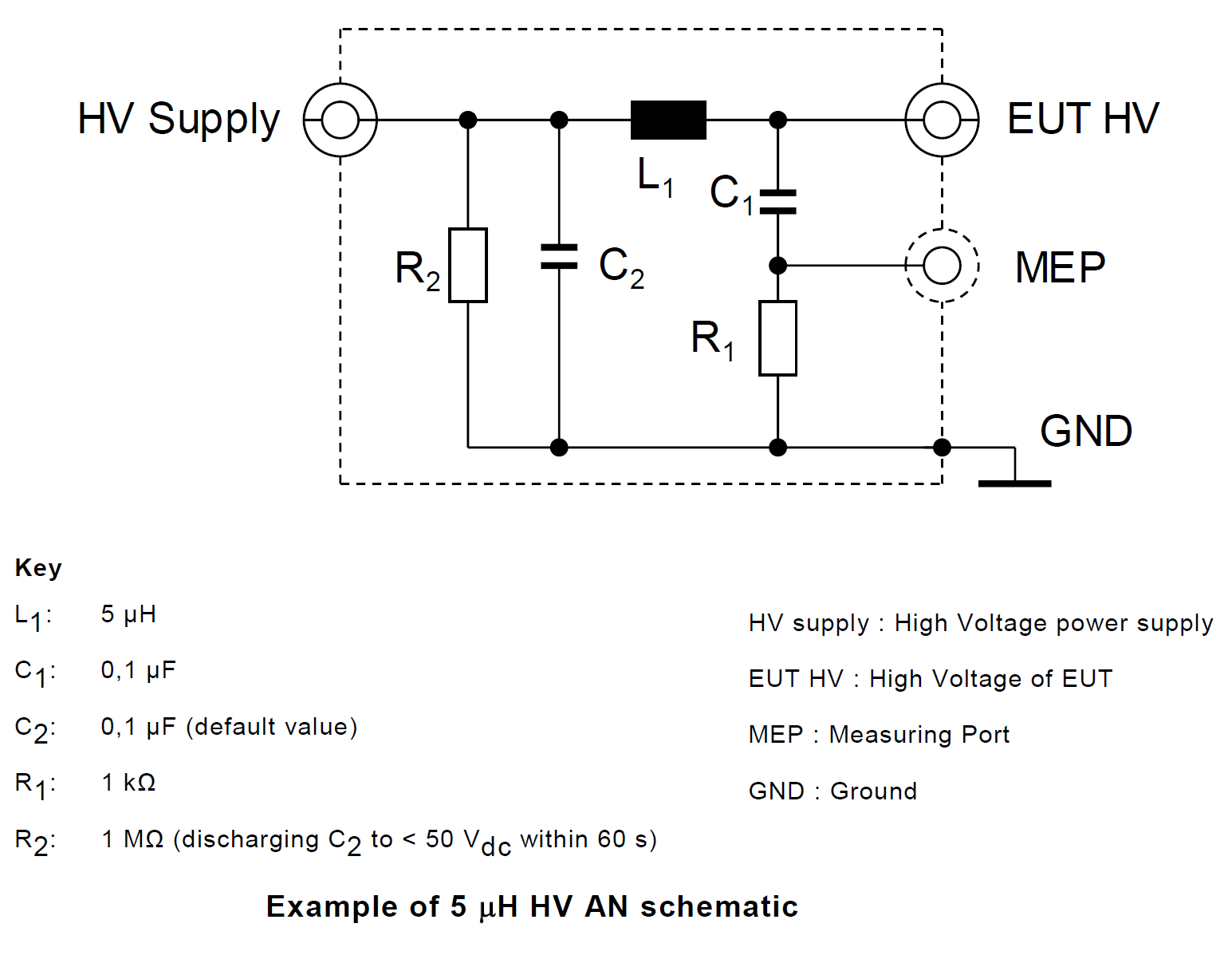
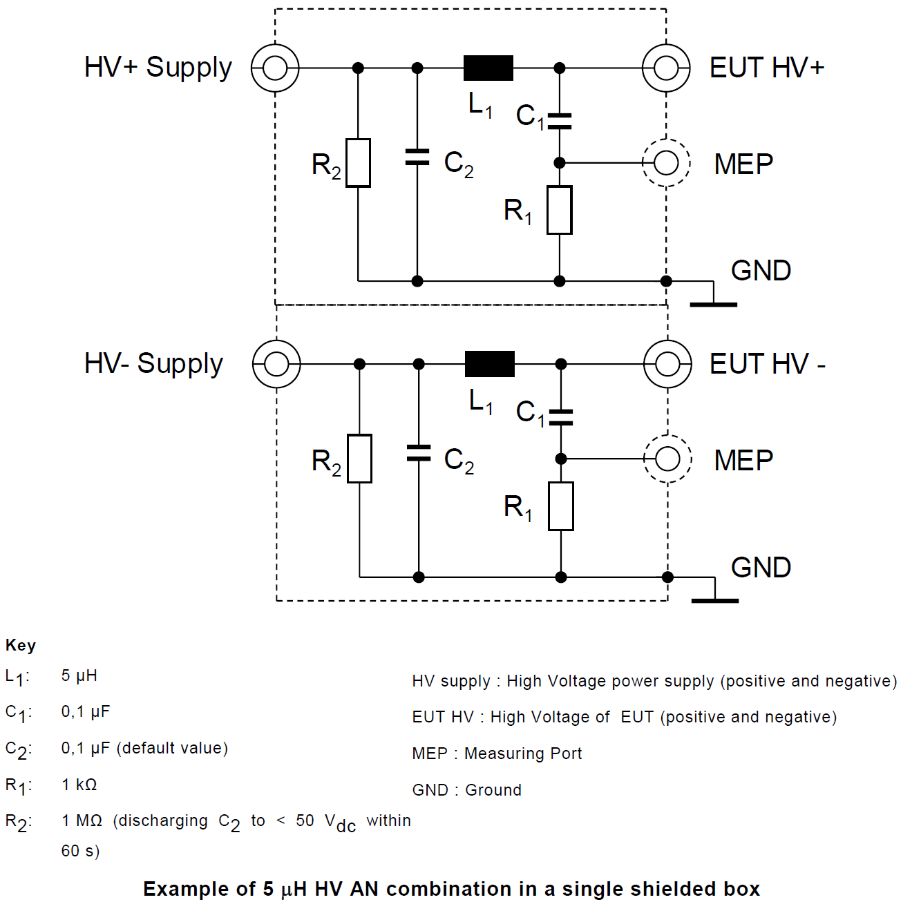
2. High Voltage Artificial Network (HV-AN)
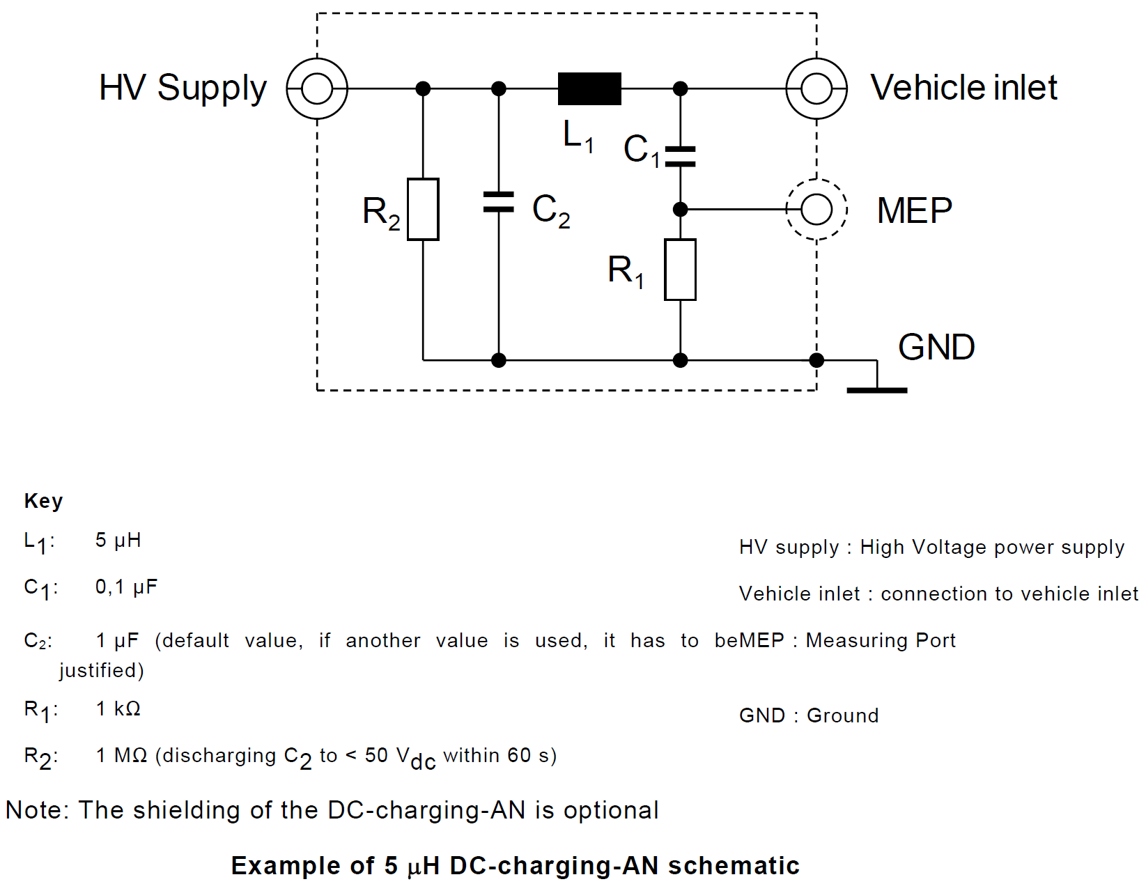
3. Direct Current charging Artificial Network (DC-charging-AN)
4. Artificial Mains Network (AMN)
Power mains must be applied to the vehicle through 50 μH/50 Ω AMN(s). The DC resistance between the ground of the AMN measurement port and the ground plane must not exceed 2,5 mΩ.
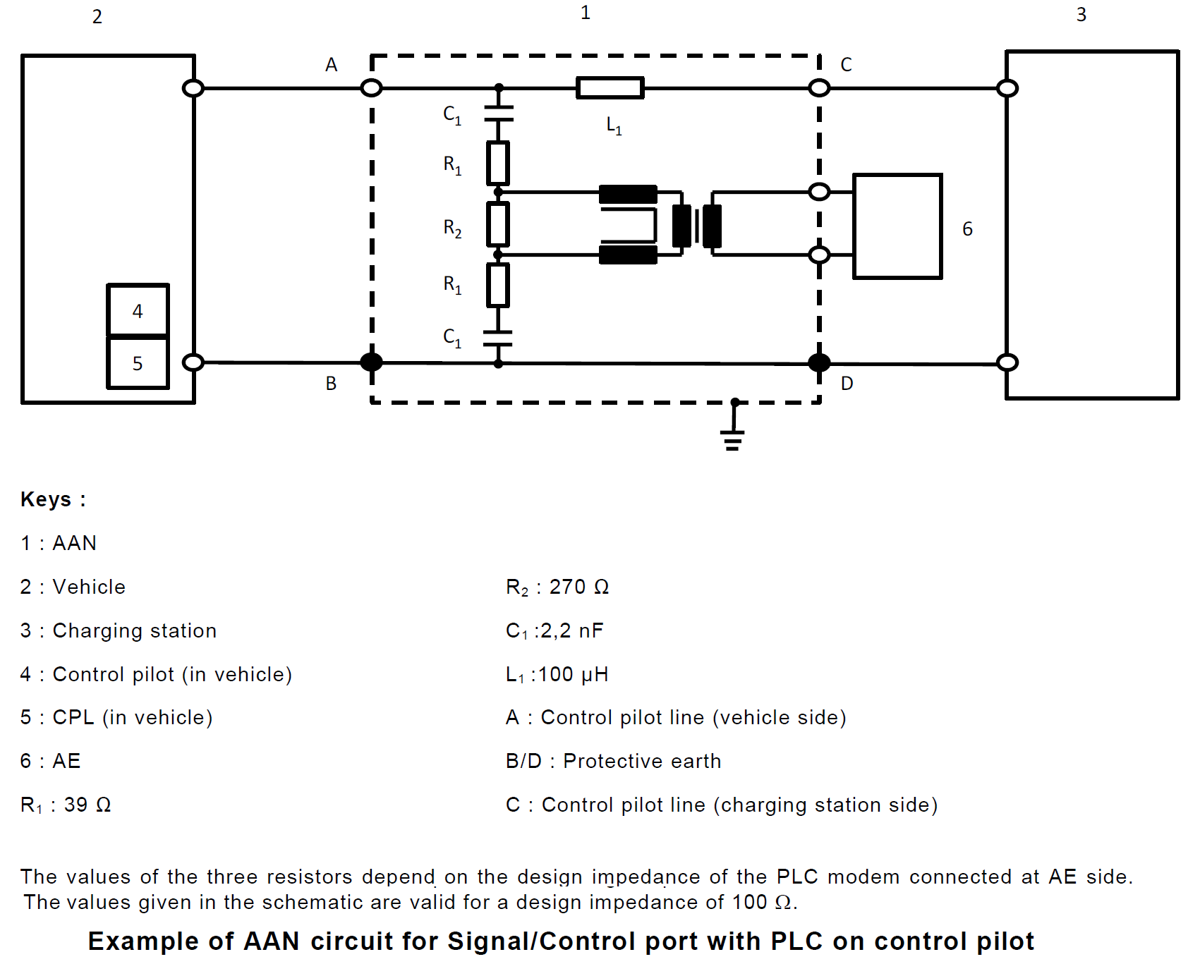
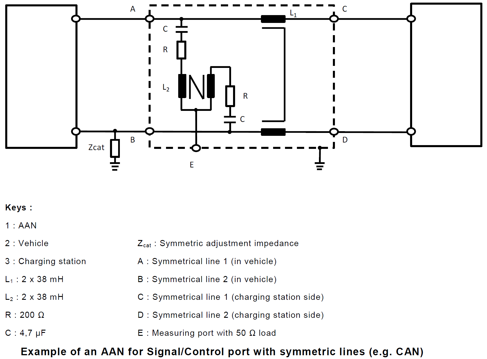
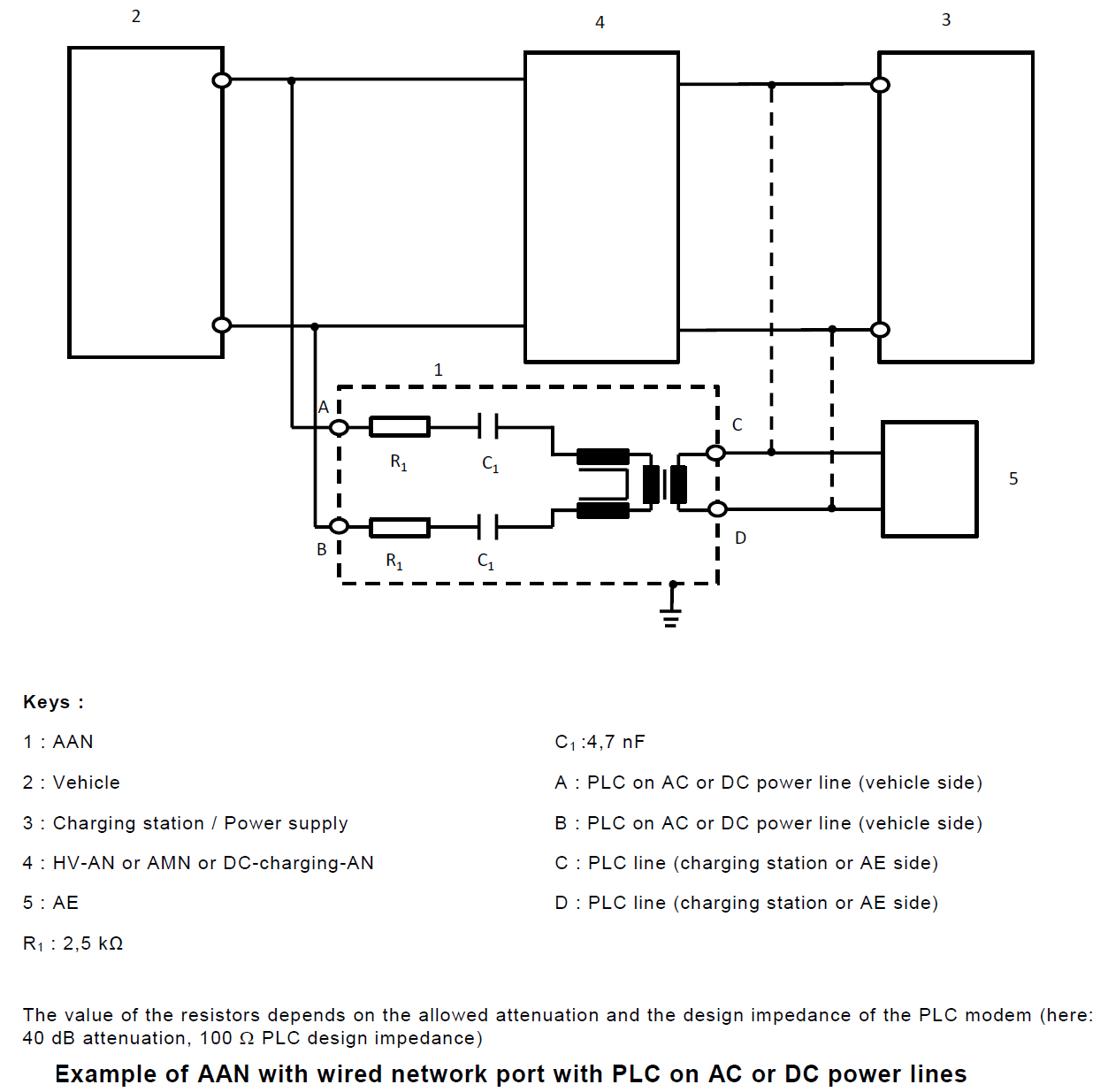
5. Asymmetric Artificial Network (AAN)
Christian Rosu
2021-06-22
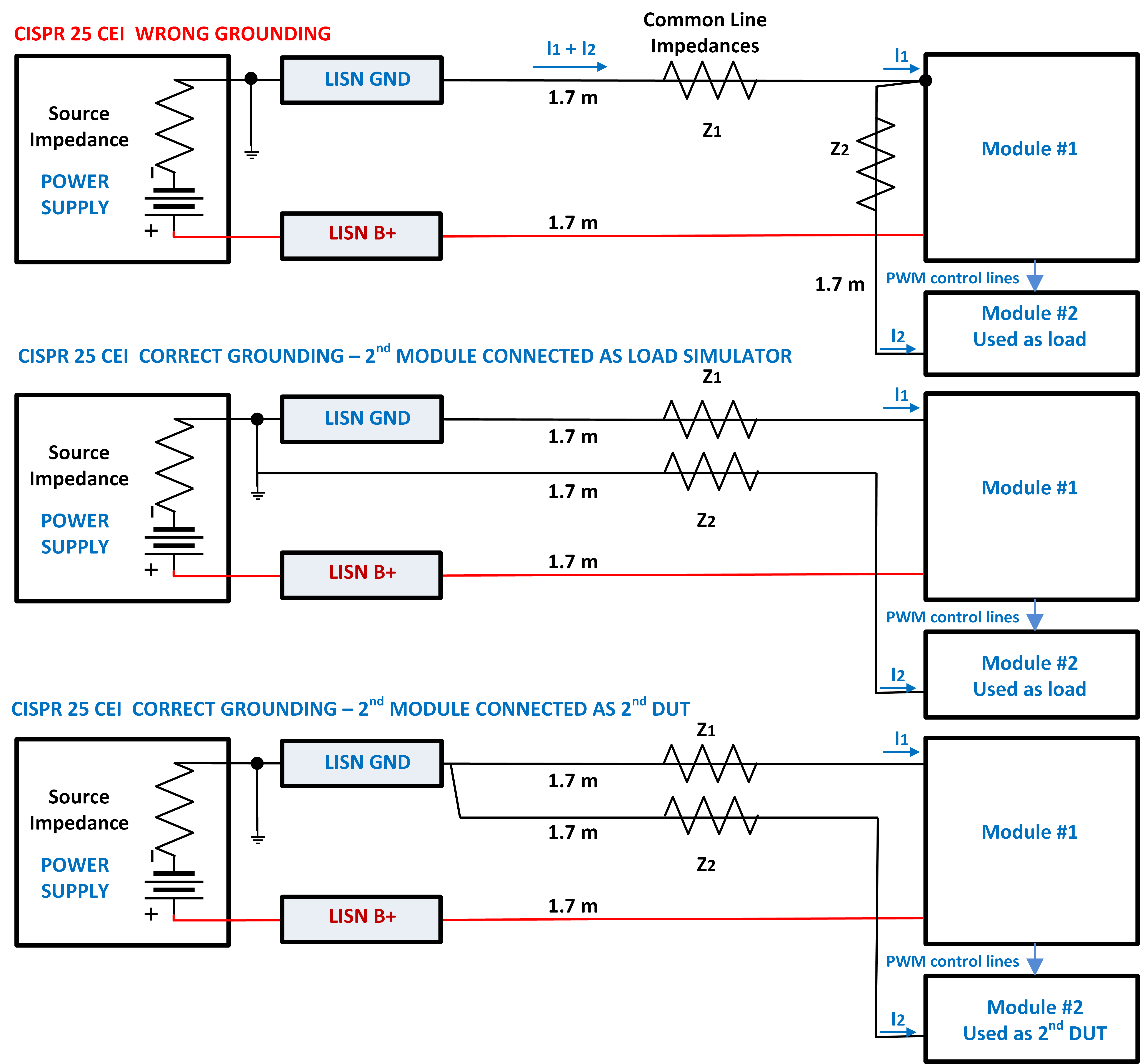
An incorrect DUT grounding scheme can easily make the difference between compliance and non-compliance to CISPR 25 CEI limits. Sometimes we have to evaluate CEI from two modules, one used as DUT and the other one used as DUT's load (e.g. Module #1 is a PWM maker while Module #2 is an LEDs Lamp).
Christian Rosu, 2021-06-09