For shielding unbalanced two-wire cables, it is critical to understand the impact of changes to ground connections to chasis vs signal return.
The signal ground for both the driver and receiver systems is defined as the internal "O V" reference for each system.
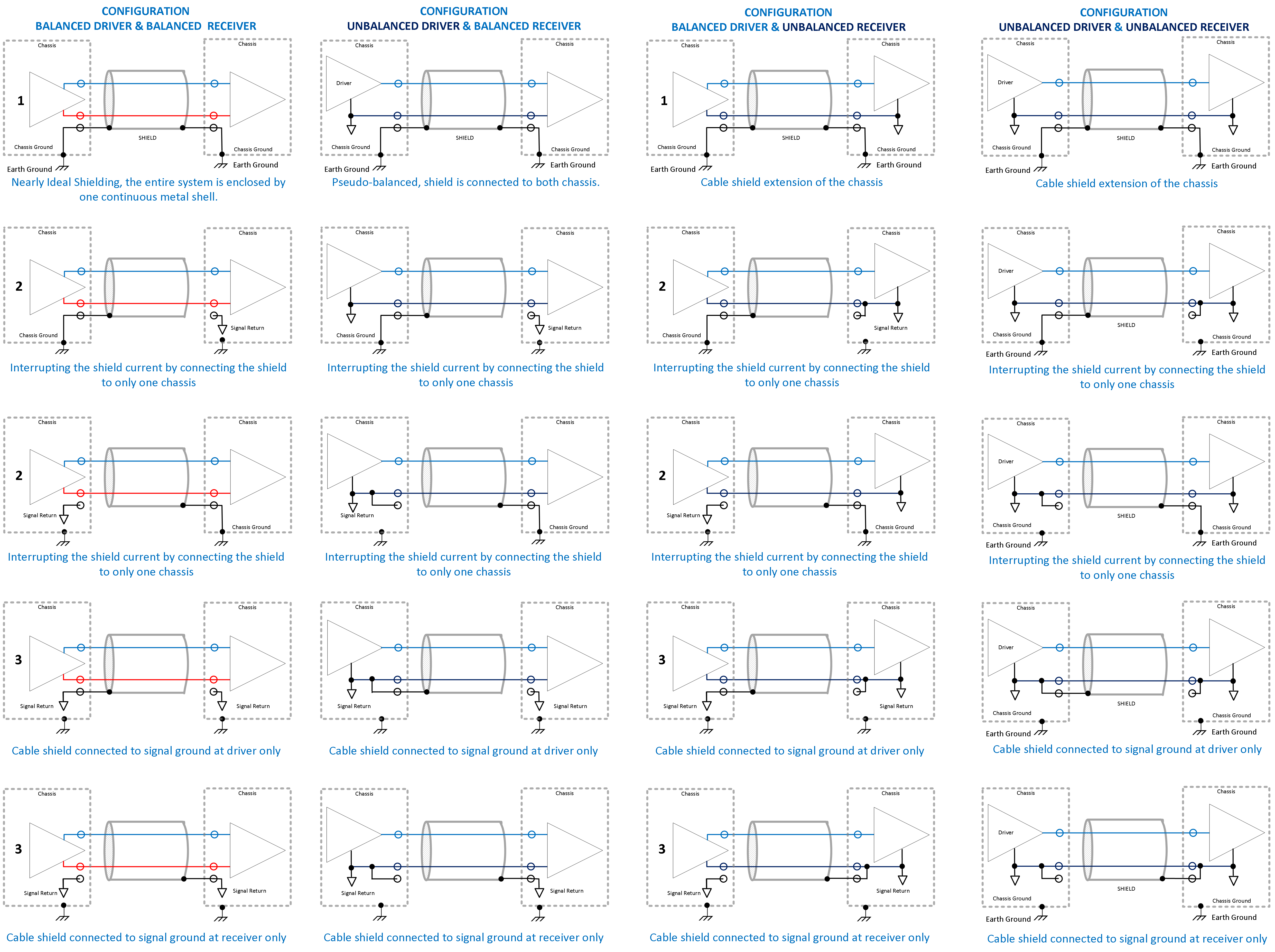
SCENARIO #1: UNBALANCED DRIVER & BALANCED RECEIVER
If the output of one device contains a balanced driver and the input of the other device contains a balanced receiver, then the nearly ideal shielding scheme is the connection of the cable shield to both of the chassis at both ends. If there are no pigtails present, then this shielding configuration is nearly ideal since the entire system is enclosed by one continuous metal shell. The cable can be viewed then as an extension of the chassis. This scenario (#1) is not perfect since the two chassis might be at two different potentials. This system can still be corrupted and unbalanced by other sources. When the chassis for driver and receiver circuitry are at different potentials, ground current will pass between the chassis and through the cable shield, forming a ground loop. Depending on factors such as the frequency, this current can appear on the inside of the cable shield and chassis. This ground loop current and the field it generates can also interfere with other systems that are not completely shielded.
Although the driver and receiver are shown as balanced, they cannot be perfectly balanced, and some of this inner shield current can induce noise into the circuit. Because the length of the connecting cable is often large compared to the largest dimensions of the two chassis, the balancing of the wires inside the cable is probably most critical. However, any current that is present along the inner surface of the two chassis can also induce noise in other nonbalanced and other nonideal balanced circuits inside either chassis.
SCENARIO #2: UNBALANCED DRIVER & BALANCED RECEIVER
In this configuration the cable shield is connected to only one of the chassis. If only one of the chassis are connected to their respective signal grounds, then the other signal ground should not be connected to the cable shield. Otherwise, noise currents induced on the chassis and cable shield would travel inside the device through this signal ground connection, partially defeating the purpose of the shielding. Although the two outputs and two inputs of the balanced driver and receiver are not connected to these signal grounds, the rest of the circuit will probably contain unbalanced circuitry that would use a signal return or ground. When both the driver and receiver chassis are connected to their respective signal grounds, then there is no clear best solution. Usually, the cable shield is not left floating. If there i no convenient way of connecting the cable shield to either chassis, the cable shield is connected to one of the signal grounds. Usually, to avoid excessive noise currents on the signal grounds, the cable shield is not connected to both of the signal grounds; one end of the cable shield is left disconnected or not tied to anything. Since the signal ground is likely connected to the chassis ground at a single point, the cable shield is at a low potential. There is a potential benefit of connecting the shield to the signal ground at both ends: the path of the noise current is well known and the crosstalk might be better controlled.
When a balanced driver connects to an unbalanced receiver, the unbalanced receiver easily amplifies noise that is picked up by the system. With balanced receivers, the receiver rejects some of the commonmode noise. For this reason, a balanced driver and unbalanced receiver combination can be very troublesome. As with the previous configurations, the 1st ranked configuration shown in Table 18.4 involves connecting the cable shield at both ends to the chassis. Again, noise currents on the cable shield can induce noise on the two conductors inside the cable. To reduce this noise or crosstalk coupling to the cable's inner conductors, the cable length should be minimized. If this noise level is too great, it may be necessary to disconnect the cable shield from one of the chassis as shown in the ranked configurations. If connection of the cable shield to a chassis is not possible, then the cable shield can be connected to either signal ground (but not usually both) as shown in the 3rd ranked ronfigurations. Care should be taken when connecting either output of the balanced driver to the signal ground of the unbalanced receiver. Essentially, the corresponding output is short circuited by this connection, which can damage the output device and cause distortion. Even connecting the output of the balanced driver to the signal ground of the receiver can be troublesome. Balanced floating drivers are available to alleviate some of these "shorting" of the output problems. Although usinga balanced driver can help in reducing the emissions from the system, it does not help (much?) for decreasing the susceptibility of the system.
SCENARIO #3: BALANCED DRIVER & UNBALANCED RECEIVER
The driver is unbalanced while the receiver is balanced. Connecting an unbalanced driver to a balanced receiver will decrease the common-mode rejection ratio (CMRR) of the entire system. As with completely balanced systems, potentially troublesome noise current can exist along the inner surface of the cable shield and chassis. Since the driver and receiver combination is not balanced in this case, the noise current can couple into the system more easily than in the case with the fully balanced system. For this reason, interrupting the conducting path for these noise currents can result in lower noise levels. Therefore, either of the 2nd ranked configurations may result in lower noise levels than the 1st ranked system. If the option of connecting the cable shield to one chassis is not available, then the cable shield should be connected to one of the signal grounds. Generally, the shield should not be left floating. It is probably a good idea not to connect the cable shield to the signal grounds at both the driver and receiver. Not connecting the shield to both signal grounds will tend to reduce the noise currents on the signal grounds by interrupting the conducting path. The 3'd ranked configuration is commonly used, especially when the actual grounding connections inside the driver and receiver are not known with certainty.
SCENARIO #4: UNBALANCED DRIVER & UNBALANCED RECEIVER
Typically, when an unbalanced driver is connected to an unbalanced receiver, coaxial cable or other two-conductor cable (no three-conductor cable is used). However, if shielded two-wire cable is used SCENARIO #4 can be referred to for grounding recommendations. The previous rationale also applies for these connections.
Generally, shielded two-wire cable when properly connected will be less susceptible to noise and have lower field emissions than unshielded two-conductor cable. The balance nature of the cable is also an important factor. Shielded two-wire cable, such as shielded twisted pair, is often balanced. To help in the balancing of the system, when connecting a balanced driver to a balanced receiver, it is highly recommended that the connecting cable also be balanced. Although shielded balanced cable is recommended, the following comments are provided in those cases where two-conductor cable is used.
Twisted pair that is not shielded is considered a two-conductor cable. Twisted pair is considered a balanced cable. When balanced twisted pair is used to connect a driver enclosed by a metal chassis to a receiver enclosed by a metal chassis, the cable shield conductor is not present to "continue" the metal enclosure of the chassis. Although not all possible combinations will be discussed, generally for twisted pairs:
- When connecting a balanced driver to a balanced receiver, neither side of the twisted pair should be connected, if possible, to either the chassis or signal grounds; otherwise, the balance of the system will be affected.
- When connecting an unbalanced driver to a balanced receiver, one conductor of the twisted pair must be connected to the signal ground at the driver to provide a return path for the driver current. Since the signal ground is likely connected to the chassis at one point, this may imply that one conductor of the cable is connected to one chassis (but not both). Neither the signal nor the chassis ground at the balanced receiver should be connected to either of the two twisted-pair conductors. Otherwise, a conductive path is available for any noise currents on the ground system.
- When connecting a balanced driver to an unbalanced receiver, one conductor of the twisted pair must be connected to the signal ground at the receiver. Additional connections to ground are normally avoided.
- When connecting an unbalanced driver to an unbalanced receiver, one conductor of the twisted pair must be connected to the signal ground at both the driver and receiver. This implies that the signal (and noise currents will return on both the cable return conductor and signal ground path.
When systems are connected with coaxial cable, the outer conductor is acting like a shield. Unfortunately, this outer conductor is also the signal return conductor. Coaxial cable has the advantage of providing some shielding, but coaxial cable has the disadvantage of being an unbalanced cable. For this reason, when coax is used to interconnect a balanced driver and receiver, it will tend to decrease the balance of the system more than twisted pair. The outer conductor of coax should be used as the signal return conductor. For this reason, the outer conductor or shield of the coax should be connected to something on both ends and not left floating. The previous recommendations for unshielded twisted pair can be applied to coax. The two conductors for the coax are the inner conductor and outer conductor. The only major difference is that the outer conductor or shield is normally connected to the more negative side of the driver and receiver.
Christian Rosu, Nov 18, 2021