Antenna Polarization (Vertical & Horizontal)
A requirement for CISPR 25 Radiated Emissions and ISO 11452-2 ALSE RF Immunity.
- The 1.7m test harness runing parallel with the edge ground plane will generate horizontal polarized emissions.
- Portions of 1.7m test harness reaching connectors positioned above the 5cm thick Styrofoam on DUT and Load Simulator would generate vertical polarized emissions requiring vertical antenna polarization to be captured.
- LS support equipment cables running over the edge of the metalic table may generate a combination of horizontal and vertical emissions.
- Folded LS support cables tend to cancel the field generating very low vertical emissions if the folding is very tight.
It is critical to eliminate the common mode currents on both 1.7m test harness and LS support cables for lowering the noise floor to minimum 6 dBuV/m under CISPR 25 limits.
In automotive EMC the DUT is normally remote grounded in one point via supply return line to the negtive pole of the 12V battery. Local grounding for DUT with metallic housing is not practical given the risk of grounding loops and rusty connections as the car is aging. Unwanted common mode currents may run along the outside of the cabe's shild:
- The cable's shield should be connected to non-current carrying parts of DUT. If the emissions noise is actually on the shield of the cable, ideally is to use connectors that have provisions for connecting or clamping the cable shield in a 360-degree bond. Using pigtail connections is a less efficient way to connect cable shields to their connector shield terminations. The longer the pigtail used, higher the expect emissions, thereore it’s recommended to use multiple short pigtails to the connector shield surrounding the internal wires. This will tend to cancel the resulting fields.
- Bonding the cable's shield to DUT's shielded enclosure may work if local grounding is acceptable for that design. Most of the time the shielded enclosure or the heatsink is capacitively decoupled from supply return.
- adding common mode chokes to DUT PCB design to minimize common mode noise sources.
- istalling an external common mode choke around DUT's end of the I/O cable.
- Expensive connectors have provisions for connecting or clamping the cable shield in a 360-degree bond, which is ideal.
Ground Loop
A noise current sharing a common return impedance with a signal current.
Confined System
When connecting signal line cables within a confined system, the shield is connected at both ends in order to provide a signal return current path.
- For high frequency digital signals above (10 to 100 kHz), proper magnetic field shielding requires a connection at both ends of the cable shield. This provides a return path for the high-frequency currents to flow back along the signal path.
- For frequencies greater than 10 to 100 kHz, the return current wants to travel the path of least impedance – that is back through the cable shield – due to mutual impedance coupling.
- For electric fields, connect only one side of the shield at the noise source (or sensitive analog) end.
Distributed System
For a system distributed across a larger area, with potential differences in the reference returns between one end of the cable and the other, the shield is connected only at the signal source end. The potential difference between the main controller digital return and and various sensor returns can be quite different. The result would be noise currents flowing in the shield. Such type of hybrid ground is used where a series capacitor is used to connect the non-source end of the shield to signal return (e.g. 300 feet long cables in aerospace industry).
Opto-isolators, differential pairs, common-mode chokes are useful to “break” any noise currents in the shielded twisted pair of sensor cables.
Audio or power line frequencies
- For fixing a ground loop issue, grounding one end of the shield or blocking the low-frequency (or DC) component with a capacitor might work best. Isolation transformers may be used for both line and audio applications.
- For signal currents greater than 10 to 100 kHz, use a solid ground bond at each end of the cable shield. Ground loops just don't tend to occur above 10 to 100 kHz.
NASA spec mention to:
- Ground one end (or use some form of isolation to break the loop) for low frequency ground loop fields.
- Ground both ends for shielding against external high frequency fields.
DUT with shielded enclosure using unshielded cable
- Minimize the common mode (noise) current loop through either diversion (back to the noise source) d or blocking with some impedance. Break (or block) the loop with common-mode chokes at the I/O connector signal lines. Add transient protection devices to guard I/O connections against ESD and other pulse-type signals.
- Insert a common-mode ferrite choke in the power and it's return lines. It's always good EMC practice to design in common-mode chokes in both the signal and power lines.
- Ensure each signal and signal return wire pair within the cable is twisted. This will achieve several dB of shielding effectiveness by itself.
- If using a ribbon cable, make sure there are adjacent signal (and power) return wires for each corresponding signal (or power) wire.
- If running a clock signal, make sure there are clock return wires on each side of the clock wire.
- If all else fails, use a clamp-on ferrite choke around the cable, positioned right at the I/O connector.
DUT with plastic (unshielded) enclosure
There will inevitably be common-mode noise sources on the PC board. To keep these noise currents off our I/O and power cables:
- block the currents from getting to the cables with a ferrite choke or
- divert the noise currents back to their source.
- A combination of blocking and diversion is the best method. Higher-end handheld consumer products use a diversion plate under the PC board. It is a thin meallic plate or metalized film with one end bonded or clamped well to the I/O and power connector ground shells. This offers a low impedance path for the common-mode currents to flow back to the source through distributed capacitance. It also protects sensitive circuitry from external ESD currents injected at the I/O connectors. In addition, it serves as an image plane which helps reduce radiated emissions. The cable shield must be bonded in some way to the digital ground (if a signal or I/O cable) and power ground (if a power cable). Ideally, all I/O connectors and power connectors should be grouped together on one side of the board. If they are spread all around the perimeter, then any noise sources on the PC board are potentially driving the midpoint of a dipole antenna.
Low Voltage Differential Signaling (LVDS)
Switches about 1.2V at very fast edge speeds. Theoretically differential signals should never radiate, but ANY unbalances in line length or routing can cause common-mode currents to form.
Solutions:
- use flat ferrite chokes
- shielding the cable and connecting the shield back to digital return in several places at each end of the shield.
Troubleshooting:
- use ferrite
- install copper tape to one side of the cable to provide a path for any unbalanced common-mode currents to return to their source.
Shielded Enclosures and Gaskets
Both the compression of the shields and gaps/cracks in the gasket may may affect slot emissions. It’s really a factor of both the manufacturer’s recommended compression, plus how well the gasket installation is designed. Minimize the length of any gaps between any two pieces of metal enclosure. The leakage can be measured using a near field probe and sliding it along all the enclosure seams. Preferable to be done in ALSE chamber.
Earth Grounding Rod
In EMC testing is needed for establishing a voltage reference, discharge high transient voltages, static discharge, personnel safety.
Pigtail connectors
Are an insulation displacement connector that are filled with a di-electric grease to prevent moisture from getting inside the connector. No need to strip the ends of the wires, just insert them into the connector, then squeeze the blue cap down with a pair of pliers.
Connectors
When the source of the radiation is from common currents on external cables such as those that connect to peripherals, using a “better” cable often has no impact at all on the radiated emissions. That’s because the common currents are flowing on the shield of the cable.
It only takes 3 μA of common current flowing on the shield of a cable, 1 m long, to cause an FCC class B failure.
The most important driving voltage for these common currents that causes EMC failures is ground bounce in the connector attaching the cable to the chassis.
Ground bounce is the voltage generated between two regions of the return path due to a changing current flowing through the total inductance of the return path.
The total inductance of the return path is related to the total number of field lines around the conductor per amp of current flowing through it. When the dI/dt of the return current flows through the total inductance of the connector, it generates a voltage, and this voltage between the chassis and the cable’s shield is what drives the common currents on the cable, which results in an EMC failure.
A coax cable will have no ground bounce because there no external magnetic field around it.
The signal current generates an external magnetic field composed of circular rings of field lines circulating in one is direction.
The return current, if symmetrical about the signal path, generates the identical rings of magnetic field around the cable, but circulating in the opposite direction. These two sets of magnetic field lines exactly cancel out and there is no external magnetic field.
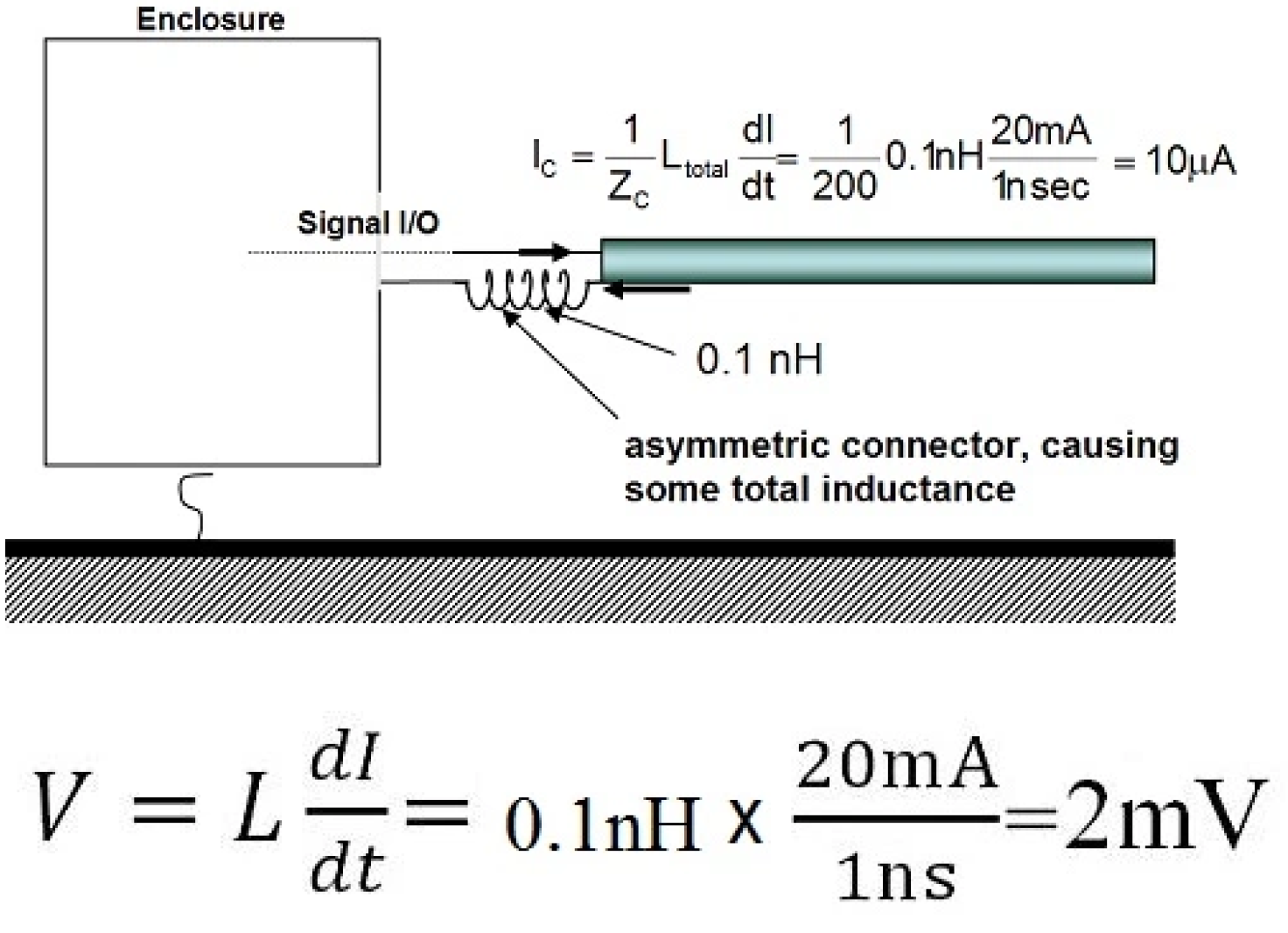
But suppose at the connector, the return current is not perfectly symmetrical about the signal current. Maybe there is a pigtail, maybe the clam shell is not well metalized, or maybe the connector only makes contact at one or two points to the chassis.
Any asymmetry will mean the magnetic field lines from the signal current and return current will not perfectly cancel out. There will be some net magnetic field lines and this will result in some total inductance of the return path.
In a 50 Ω coax cable, with a 1V signal, having a 1ns rise time, the signal and return current is about 1 V/50 Ω = 20 mA.
Even if the asymmetry is so light as to generate only 0.1 nH of total inductance around the return path of the connector, the ground bounce voltage generated would be 2 mV.
If the impedance the common current sees returning through all those fringe field lines is about 200 Ω, this 2 mV of ground bounce voltage will drive I = 2 mV/200 Ω = 10 μA.
It only takes 3 μA of common current to fail an EMC certification test.
This ground bounce driven current in the cable shield will cause an EMC failure.