EMC FLEX BLOG A site dedicated to Automotive EMC Testing for Electronic Modules

DUT configuration for CISPR 25 ALSE chamber ambient

28. October 2020 07:03 by Christian in EMC/EMI, EMC TEST PLAN, OEM Specs, Standards, Test Methods
The automotive OEM specs do not specify how to configure the DUT during CISPR 25 chamber ambient measurements.

The automotive OEM specs do not specify how to configure the DUT during CISPR 25 chamber ambient measurements. DUT must be unpowered, all other DUT support equipment must be powered and as much as possible functional to correctly evaluate RF emissions noise floor before start testing. This leaves at least three scenarios for how to configure the DUT.

 
1) Disconnect the DUT from test harness. 
  1.  Test harness connectors are removed from
  2.  DUT is unpowered.
  3.  The 1.7 m test harness is unterminated on DUT side, no potential ground loops with Load Simulator.
  4.  The 5uH LISN remains present.
  5.  The Load Simulator and all support equipment remains powered.
 
2) Disconnect DUT's B+ line from LISN output.
  1.  Test harness connectors are plugged into DUT.
  2.  DUT is unpowered by disconnecting B+ line LISN input from Battery.
  3.  The 1.7 m test harness terminated on both ends, therefore potential ground loops with Load Simulator are possible.
  4.  The 5uH LISN remains present.
  5.  The Load Simulator and all support equipment remains powered.
 
3) Diconnect DUT's B+ line from LISN output.
  1.  Test harness connectors are plugged into DUT.
  2.  DUT is unpowered by disconnecting DUT B+ line from LISN output.
  3.  The 1.7 m test harness terminated on both ends, therefore potential ground loops with Load Simulator are possible.
  4.  The 5uH LISN is not present anymore, and this somehow violates CISPR 25 requirement.
  5.  The Load Simulator and all support equipment remains powered.
 
Christian Rosu

CISPR-25 RE per CS.00054:2018

15. October 2019 10:00 by Christian in EMC/EMI, OEM Specs, Test Equipment, Test Methods
CISPR-25 Generic Test Setup for compliance to CS.00054:2018.

CISPR-25 Generic Test Setup for compliance to CS.00054:2018

CS.00054 Radiated Emissions Block Diagram
 
The vertical monopole element is centered at 1m from the center of the 1.7m test harness. Note that 1.5m of the harness is running at 10 cm parallel with ground plane edge. The antenna counterpoise is placed +10/-20 mm vs GP. 
 
CISPR-25 Generic DUT Setup. The DUT is placed @ 20 cm from the edge of GP. The 1.7 m Test Harness is routed 90 degrees towards DUT.
 
The ground plane is connected to chamber's floor to a dedicated Earth Grounding Rod.
 
LISN (700 V DC / 500 A) & Load Simulator side of the test setup. 
DUT's B+ & GND lines are connected to LISN's outputs.
 
THE BICONICAL ANTENNA IN VERTICAL POLARIZATION. 
The antenna is centered on the 1.5m harness running at 10 cm parallel with GP edge.
 
THE BICONICAL ANTENNA IN HORIZONTAL POLARIZATION. 
The antenna is centered on the 1.5m harness running at 10 cm parallel with GP edge.
 
THE LOG PERIODIC ANTENNA IN VERTICAL POLARIZATION. 
The tip of antenna is 1 m away from the center of the test harness.
 
THE LOG PERIODIC ANTENNA IN HORIZONTAL POLARIZATION. 
The tip of antenna is 1 m away from the center of the test harness.
 
Octave Antenna Vertical Polarization with its aperture centered on DUT at 1 m distance from test harness.
 
Octave Antenna Horizontal Polarization with its aperture centered on DUT at 1 m distance from test harness.
 
Horn Antenna Horizontal Polarization with its aperture centered on DUT at 1 m distance from test harness.
 
Horn Antenna Vertical Polarization with its aperture centered on DUT at 1 m distance from test harness.


3-METER ALSE CHAMBER & Equipment Control Shielded Room.
 

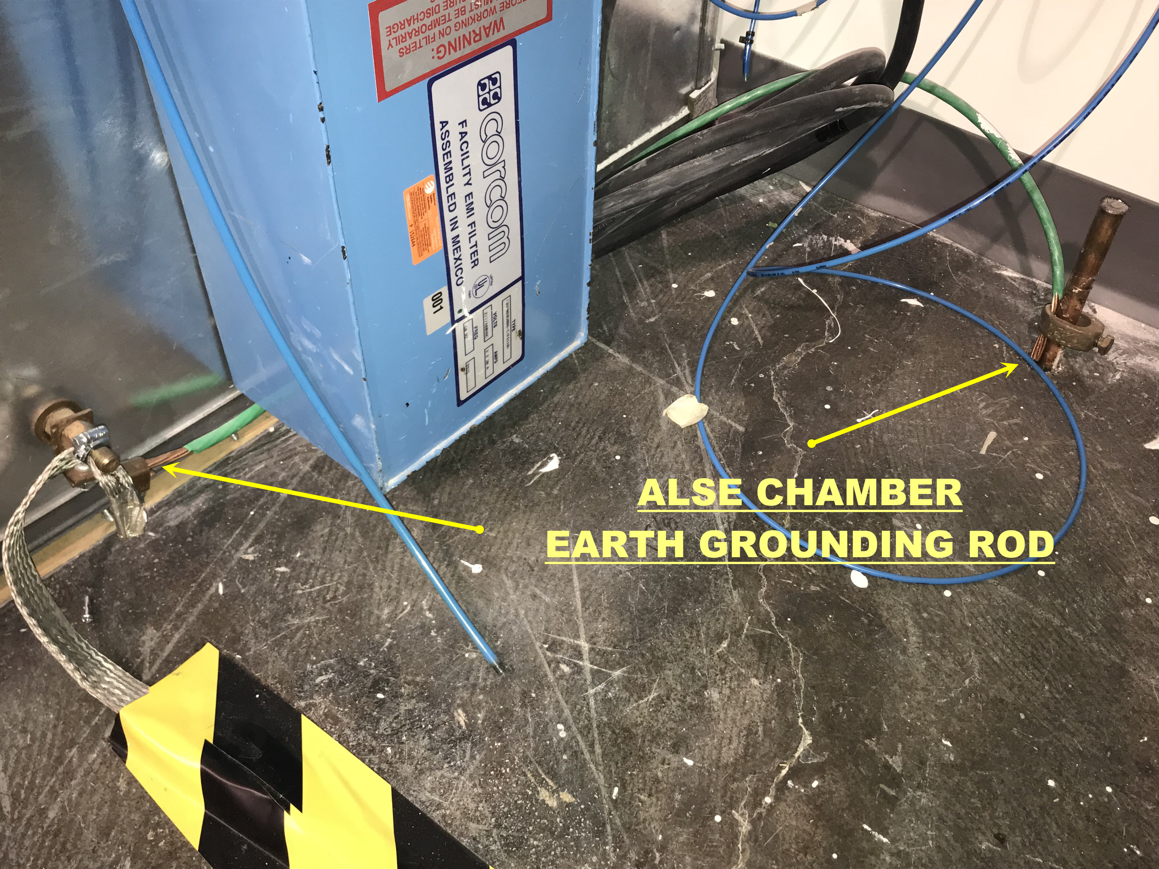
ALSE CHAMBER EARTH GROUNDING ROD.