22. December 2020 06:33 by Christian in
The Intermodulation Interference (IM) occurs when the two transmitters are in close proximity and their signals mix in one or both of their final amplifiers. This generates unwanted signals at the sum and difference of the original frequency transmissions.
Passive Intermodulation (PIM) is an intermodulation distortion that occurs in linear devices (e.g. cables, connectors and antennas) as unwanted signals created by the mixing of two or more strong RF signals due to a loose or corroded connector, or nearby rust.
Antenna factor when properly applied to a field strength meter reading yields:
- electric field intensity (V/m)
- magnetic field intensity (A/m).
The field intensity in the far-field radiation pattern of an antenna:
- Is proportional to the square root of the effective radiated power. Increasing the effective radiated power four times , the field intensity will be doubled.
- Is direct proportional to antenna current. If the far-field intensity in the far-field antenna pattern is doubled the antenna current will increase 2 times.
16. December 2020 15:52 by Christian in
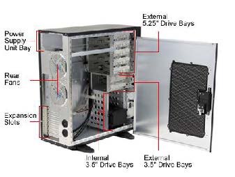
EMC/EMI, Shielding Shielded enclosure example:

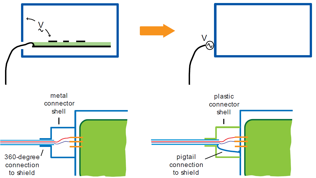
Shielded enclosure connector types:

See Troubleshooting RF Noise and Fixing Ground Loops
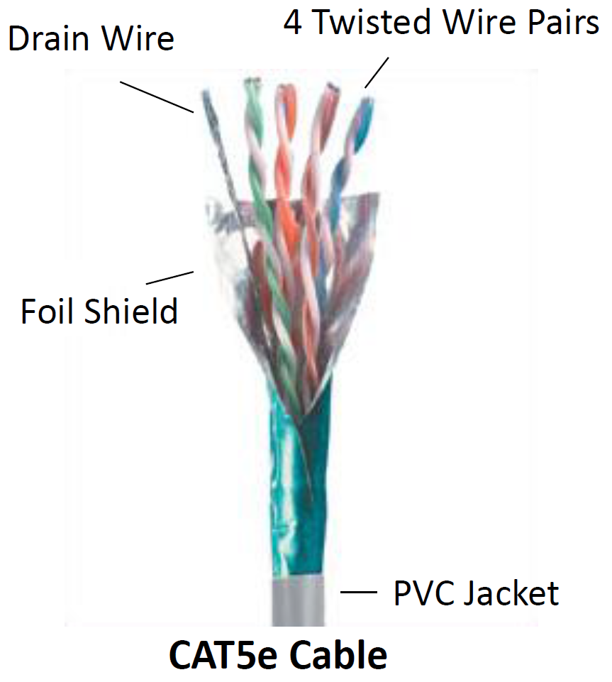
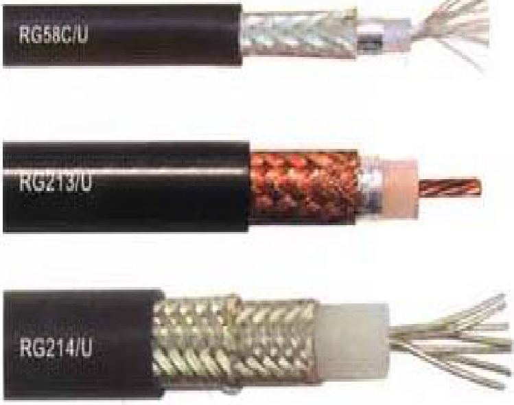
Shielded cable types:

- Foil provides high-frequency shielding.
- Drain wire carries most of the low- frequency current.

- Foil provides high-frequency shielding.
- Braid carries high-currents.
Why Cable Shielding?
- Serves different purposes in different applications.
- Sometimes carries intentional signal currents. This is an example of self-shielding.
- May prevent coupling of external electric or magnetic fields to signals carried by wires in the cable.
- Beware of transfer impedance data. It should only be used to compare similar cables for a similar application measured with the same test set-up.
Summary of Main Points:
- Electric field shielding, magnetic field shielding, cable shielding and shielded enclosures are very different concepts requiring different materials and
approaches. - It is important to be understand the coupling mechanism you are attempting to attenuated before coming up with a shielding strategy.
- Electric field shields terminate or redirect electric fields. Where they are “grounded” is often critical.
- Magnetic field shields redirect the magnetic field. Magnetic fields cannot be terminated.
- Low frequency (<kHz) magnetic fields must be redirected with high permeability materials.
- High frequency magnetic fields can be redirected with good conductors of sufficient thickness.
- Shields and imperfect shielded enclosures can significantly increase radiated emissions.
- Shields reduce radiated emissions by disrupting the coupling from near-field sources and the “antennas” in a system.
- In the near field, shields are either electric or magnetic field shields that redirect high-frequency current flow.
For a radio (transmitter or receiver) to deliver power to an antenna, the impedance of the radio and transmission line must be well matched to the antenna's impedance.
The parameter VSWR is a measure that numerically describes how well the antenna impedance is matched to the radio or transmission line it is connected to.
The voltage component of a standing wave in a uniform transmission line consists of the
- forward wave (with complex amplitude
 ) superimposed on the
 - reflected wave (with complex amplitude
 ).
).
A wave is partly reflected when a transmission line is terminated with other than an impedance equal to its characteristic impedance.
The reflection coefficient  can be defined as:
 = Vr / Vf
 is a complex number that describes both the magnitude and the phase shift of the reflection. The simplest cases with
  measured at the load are:
-
 complete negative reflection, when the line is short-circuited,
 -
 no reflection, when the line is perfectly matched,
 -
 complete positive reflection, when the line is open-circuited.
The voltage standing wave ratio is then:
See Tutorials