30. July 2015 07:39 by streng in
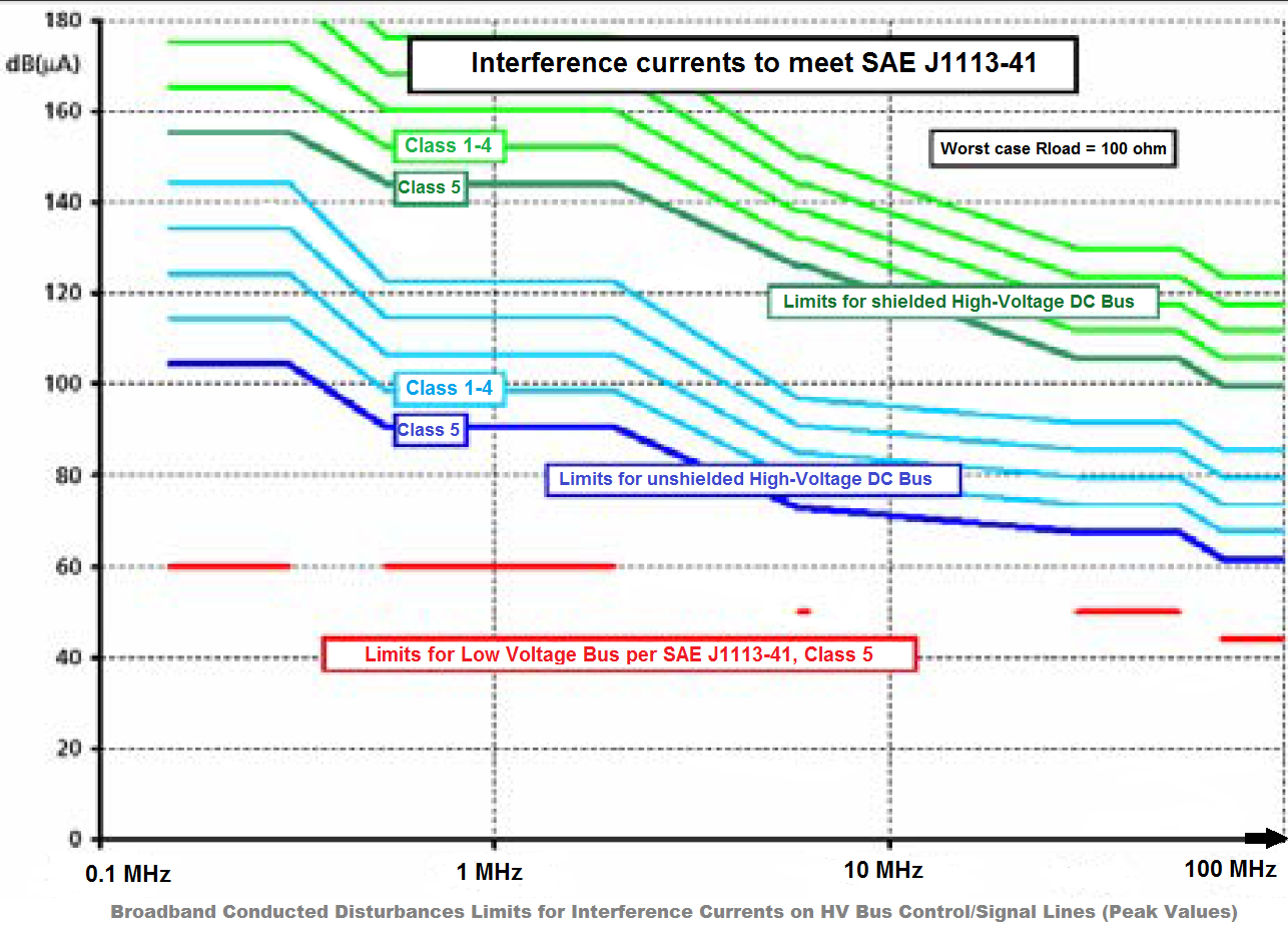
EV require higher power for the electric drive components and higher voltage (900 V) in the high voltage bus. The HV Bus is built as a completely insulated power supply network with cables most often shielded.
The main components of the automotive electric drive are:
- electric motor (the connection between converter and motor must be very short)
- power converter (the main source of EMI due to high speed switching devices with changing pulse patterns)
- power supply (traction battery providing power to the converter is a main part of the path for EMI)
- lines connecting the above components
Each of these components acts as a path for electromagnetic emissions:
- RF noise emissions due to the ratio between the size of the power converter and the frequency of the EMI.
- The high-voltage system is insulated and does not use the car body as return conductor like the low-voltage supply system. However, the high-voltage and the low voltage cables are arranged closely to each other, one important coupling path being the crosstalk between the different lines.
- The drive system can be either noise source or part of the coupling path within EV electrical system.
10. July 2015 18:34 by streng in
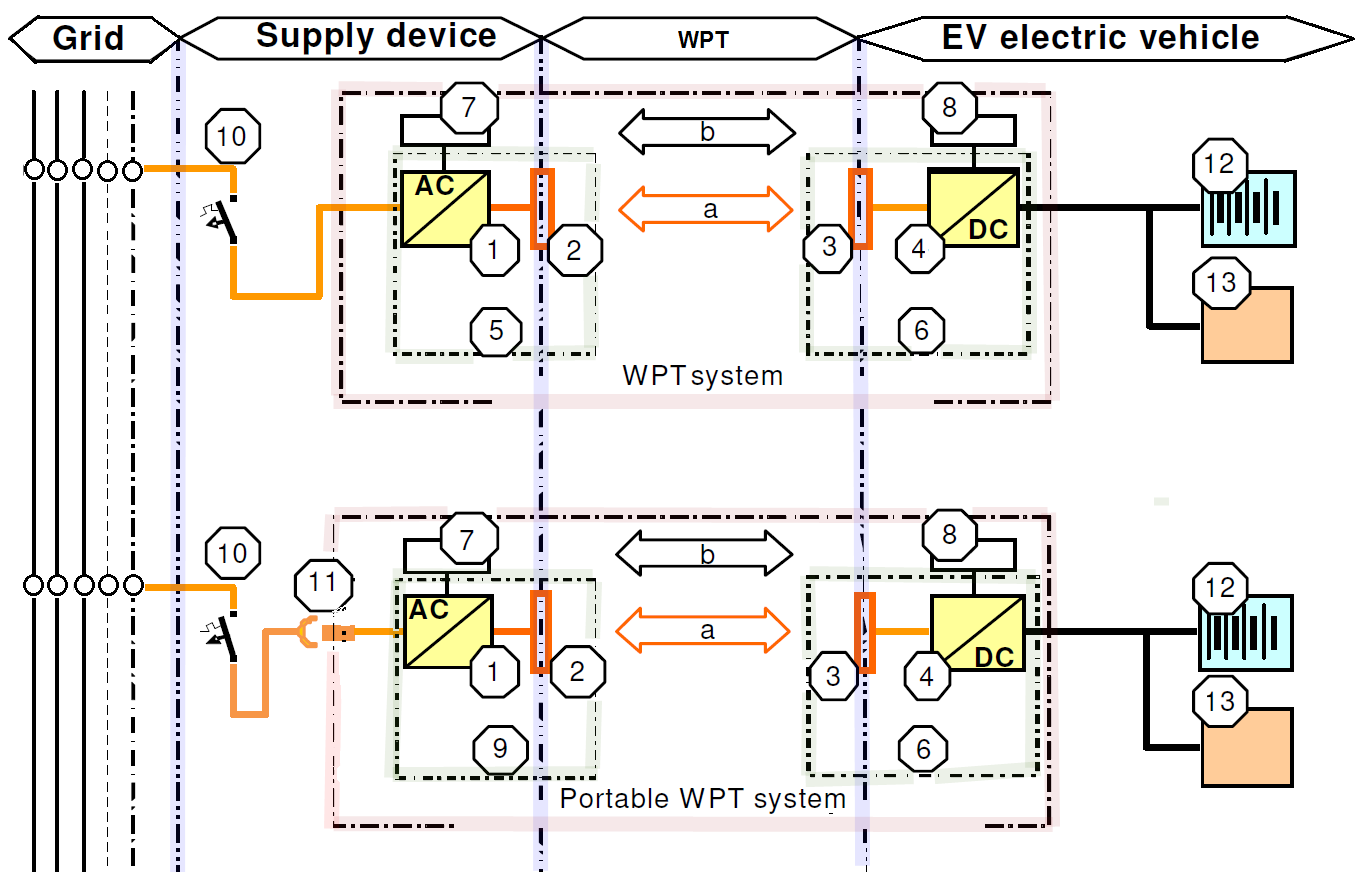
1) Off-board components
2) Primary Device
3) Secondary Device
4) On-board power components
5) EV supply equipment
6) WPT vehicle power supply circuit
7) Supply equipment communication controller
8) Electric vehicle communication controller
9) Portable EV supply equipment
10) CB & RCD or RCBO
11) Plug & socket-outlet
12) RESS or traction battery
13) Electric load
a) Wireless power transfer
b) Communication according to IEC 61980-2
12. June 2015 08:39 by streng in
MF-WPT is the wireless transfer of energy from a power source to an electrical load via a magnetic field.
Magnetic coupling
The source of a magnetic flux is a coil structure. Power transfer will be initiated by positioning two or more coil structures near each other in a way that the time varying flux generated by the primary coil structure, passes through the windings of the secondary coil structure.
Primary and secondary coil structures for WPT systems interact through an air gap. Usually a centre plane in the air gap can be defined dividing the WPT system whereas the primary coil structure is completely located on one side of this plane and the complete coil structure of the secondary device is located on the other side of the plane. For a primary device and a secondary device to be interoperable, they shall be magnetically compatible.
MF-WPT Functions
- stand by and wake up: the supply device is woken up by the a signal from the EV.
- compatibility check: power classes, the operating frequency, magnetic coupling, circuit topology, tuning.
- initial alignment check: primary and secondary devices are properly well positioned relative to each other.
- start power transfer: transfer the power from the primary device to the secondary device upon the request from the vehicle
- time scheduled power transfer: no perform power transfer until the command and control communication is properly established and the primary device and secondary device are properly positioned.
- perform power transfer: MF-WPT system transfer the power from the primary device to the secondary device in accordance with the power demand of the EV. The maximum transferring power of the off-board MF-WPT system shall not be exceeded. The vehicle can change the requested transfer power.
- stop power transfer: MF-WPT system shall be able to stop transfer the power from the primary device to the secondary device in accordance with the demand of the EV. Th e vehicle can requested stop power transfer.
- user initiated stop power transfer: allow the user to terminate of power supply. e.g. pushing stop button.
- safety monitoring & diagnostics: command & control communication safety monitoring & diagnostics
- power transfer monitoring
- thermal monitoring
- live object protection
- failure conditions: short-circuit, earth leakage, excess temperature, insulation failure, overcurrent, overload
- continuous monitoring of power transfer conditions: the actual output power does not differ from the expected output power by a certain limit; if the limit is exceeded, it shall stop power transfer.
- continuous monitoring of command & control communication
- continuous monitoring of safety conditions
- Verify that the ventilation system of the area is functioning and active
10. June 2015 18:06 by streng in
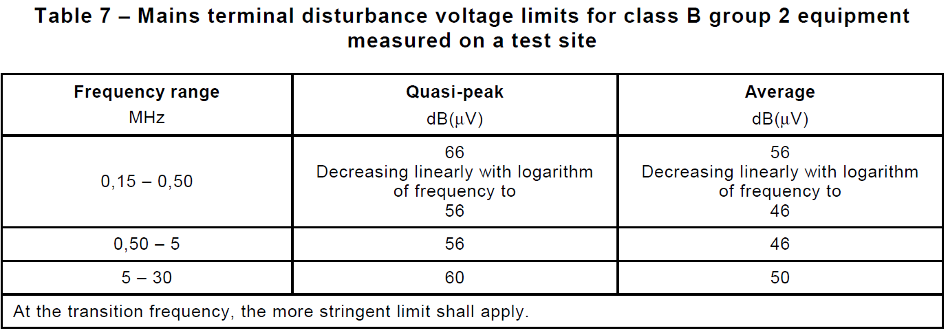
CISPR11:2010 (Ed 5.1) applies to industrial, scientific and medical (ISM) electrical equipment operating in the frequency range 0 Hz to 400 GHz. Certain frequencies are designated by the International Telecommunication Union (ITU) for unrestricted radiation from ISM equipment.
AC Power Port - CISPR 11; Conducted disturbances (150kHz-30MHz)
Table 6 (Class A) - Mains terminal disturbance voltage limits for class A group 2 equipment measured on a test site

Table 7 (Class B) - Mains terminal disturbance voltage limits for class B group 2 equipment measured on a test site
WPT System and Enclosure Port - CISPR 11;
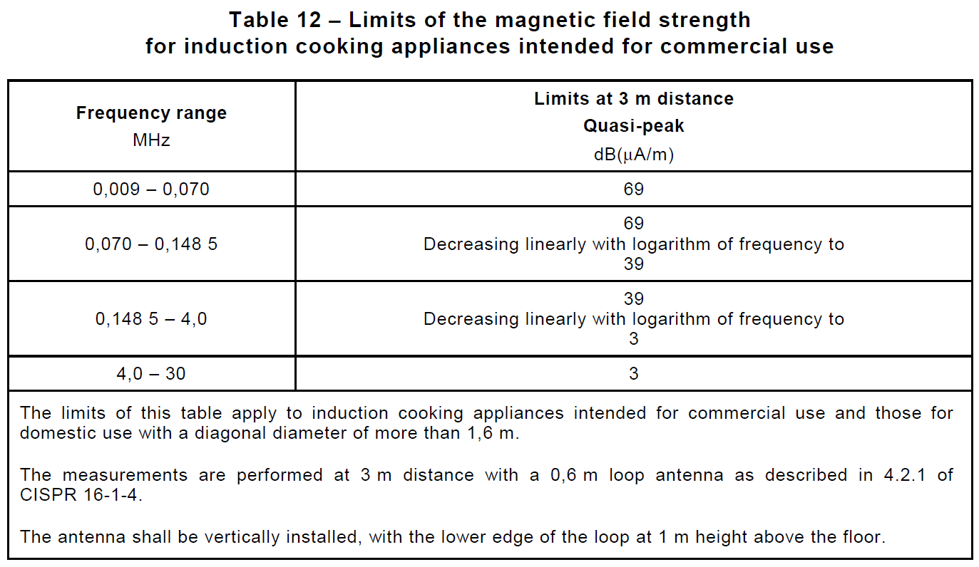
Table 12 - Limits of the magnetic field strength for induction cooking appliances intended for commercial use
WPT System Port - CISPR 11;
Table 6 (Class A) - Mains terminal disturbance voltage limits for class A group 2 equipment measured on a test site
Table 7 (Class B) - Mains terminal disturbance voltage limits for class B group 2 equipment measured on a test site