EMC FLEX BLOG A site dedicated to Automotive EMC Testing for Electronic Modules

CISPR-25 RE per CS.00054:2018

15. October 2019 10:00 by Christian in EMC/EMI, OEM Specs, Test Equipment, Test Methods
CISPR-25 Generic Test Setup for compliance to CS.00054:2018.

CISPR-25 Generic Test Setup for compliance to CS.00054:2018

CS.00054 Radiated Emissions Block Diagram
 
The vertical monopole element is centered at 1m from the center of the 1.7m test harness. Note that 1.5m of the harness is running at 10 cm parallel with ground plane edge. The antenna counterpoise is placed +10/-20 mm vs GP. 
 
CISPR-25 Generic DUT Setup. The DUT is placed @ 20 cm from the edge of GP. The 1.7 m Test Harness is routed 90 degrees towards DUT.
 
The ground plane is connected to chamber's floor to a dedicated Earth Grounding Rod.
 
LISN (700 V DC / 500 A) & Load Simulator side of the test setup. 
DUT's B+ & GND lines are connected to LISN's outputs.
 
THE BICONICAL ANTENNA IN VERTICAL POLARIZATION. 
The antenna is centered on the 1.5m harness running at 10 cm parallel with GP edge.
 
THE BICONICAL ANTENNA IN HORIZONTAL POLARIZATION. 
The antenna is centered on the 1.5m harness running at 10 cm parallel with GP edge.
 
THE LOG PERIODIC ANTENNA IN VERTICAL POLARIZATION. 
The tip of antenna is 1 m away from the center of the test harness.
 
THE LOG PERIODIC ANTENNA IN HORIZONTAL POLARIZATION. 
The tip of antenna is 1 m away from the center of the test harness.
 
Octave Antenna Vertical Polarization with its aperture centered on DUT at 1 m distance from test harness.
 
Octave Antenna Horizontal Polarization with its aperture centered on DUT at 1 m distance from test harness.
 
Horn Antenna Horizontal Polarization with its aperture centered on DUT at 1 m distance from test harness.
 
Horn Antenna Vertical Polarization with its aperture centered on DUT at 1 m distance from test harness.


3-METER ALSE CHAMBER & Equipment Control Shielded Room.
 

ALSE CHAMBER EARTH GROUNDING ROD.

RI 115 "ALSE chamber open door" test configuration

5. June 2017 09:22 by Christian in
A few months ago I was surprised that UL lab (Novi, MI) runs RI 115 (Immunity to Hand Port

A few months ago I was surprised that UL lab (Novi, MI) runs RI 115 (Immunity to Hand Portable Transmitters) leaving the ALSE chamber door fully open. I have requested the test engineer to confirm that he follows correctly UL lab internal test procedure. The response was that this is practically near field RF immunity, therefore there is no concern to interfere with other lab test equipment.


This is completely false, the reason for closing ALSE chamber door during RF immunity is to evaluate the DUT performance in a noise free environment with minimum of reflections from the chamber's walls. By opening ALSE chamber door RF emissions from nearby test equipment, broadcast and mobile services may be reflected from walls affecting DUT performance simultaneously with the intended RF near field.

I would be very curious to understand how was possible for A2LA to certify such test setup. Is this "open door" RI 115 configuration acceptable for Ford?


CISPR-25 RF emissions ambient test pitfalls

25. April 2017 15:48 by Christian in EMC/EMI, EMC TEST PLAN, Standards
CISPR-25 is not very specific in regards to chamber ambient test setup configuration in regards to d

CISPR-25 is not very specific about device under test and support equipment configuration during chamber ambient test. The automotive OEM require the ambient for RE, CE-V, CE-I with support equipment energized. The test laboratories will typically disconnect VBATT line from LISN output. The GND line remains connected to LISN. By doing so is assumed that DUT is not energized. The support equipment remains connected to the input of the LISNs being turned on (energized). The CAN bus is powered but w/o traffic. It is unclear if the load simulator energized it means powered but inactive (standby). By activating PWM pulses as inputs for DUT it may yield unwanted CE-I and RE ambient noise. All these aspects must be clarified in the EMC test plan.

In the sample presented the CE-V ambient noise is well below the 6 dB requirement. However, this type of noise is being captured while DUT's integrated buttons are being pressed and released via a pneumatic system with no electrical connection to DUT or test ground plane. Specifying that DUT must be unpowered may not be enough, the DUT's buttons should not be mechanically activated, nor its inputs subjected to electrical signals.

 
Christian Rosu

RI 115 copy and paste fake report

22. April 2017 02:28 by Christian in
The automotive OEM that certifies EMC laboratories to carry out validation testing invested a lot of

The automotive OEM that certifies EMC laboratories to carry out validation testing invested a lot of trust in accuracy and correctness of so called "sign-off" reports. This "sign-off test results"  or "not for sign-off test results" statement maybe an excuse for skipping a full review if the summary looks clean.

The automotive electronic device supplier must always verify in detail the report to clarify each reported non-conformance. Otherwise it may adversely affect the entire validation process through endless testing to fix potential false issues.

The sample of bad report shown below may easily go undetected by those searching for easy resolutions (pass / fail). 
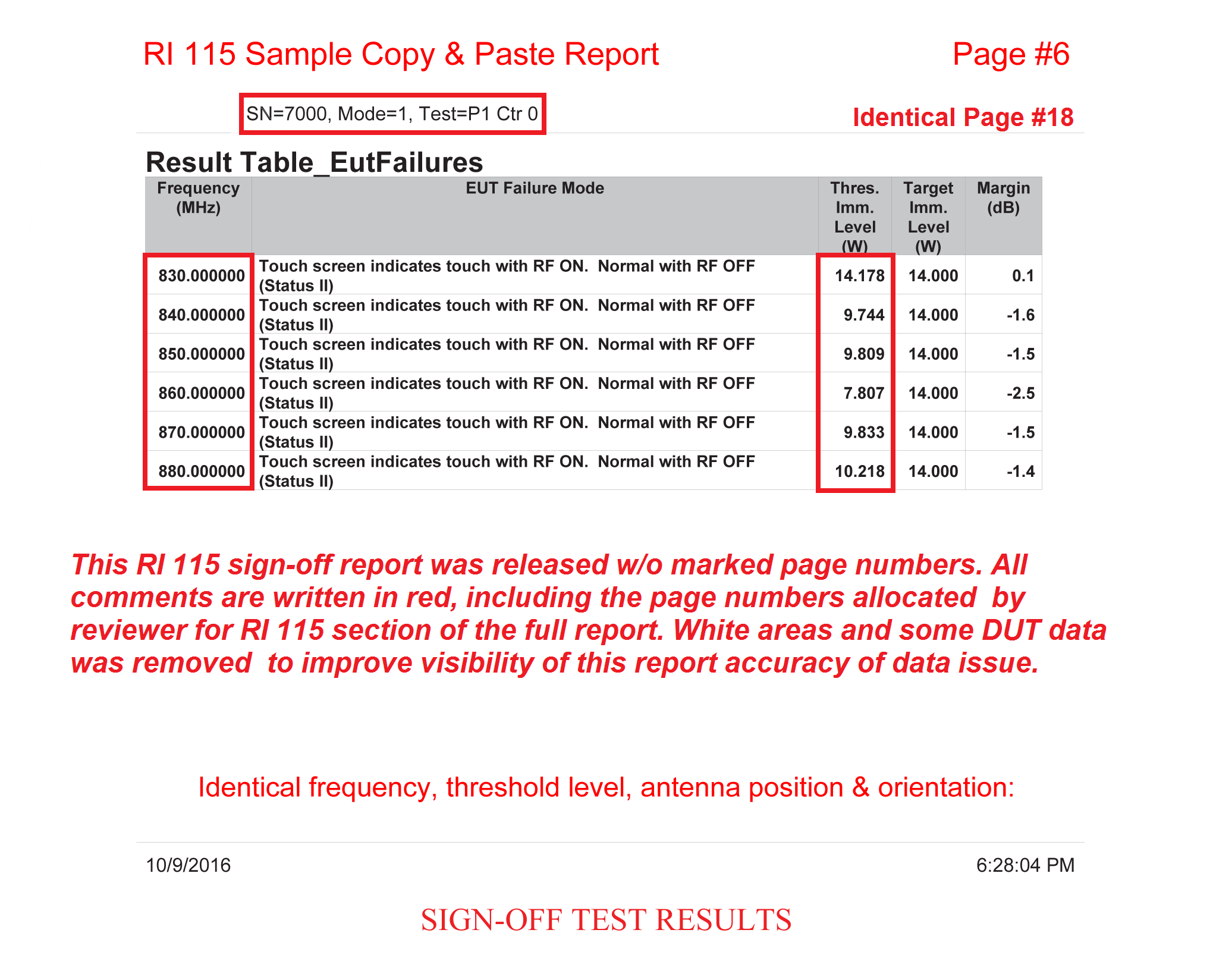
Page #6 vs Page #18

In tis particular case two samples (7000 & 7002) are being evaluated for near filed interferences from portable transmitters.

The requirement for DUT in question is to pass Level 1 in band#9 (no deviation allowed under 7 Watts). The testing is carried out at 14 Watts, which is the Level 2 Severity. Whenever a deviation occurs the test operator must threshold the lowest severity level where the problem goes away.

The issue with the above result is that the same severity level threshold result was copied from one sample to another (7002 to 7000). It is impossible to have identical 3-digit accuracy readings between two test samples for the same antenna position and orientation. In fact, considering the uncertainty of test equipment combined with HW/SW tolerances of DUT it is impossible if scanning the same sample twice. The test result data file is generated automatically by the software running the test equipment. Chances to be a copy and paste mistake are zero.
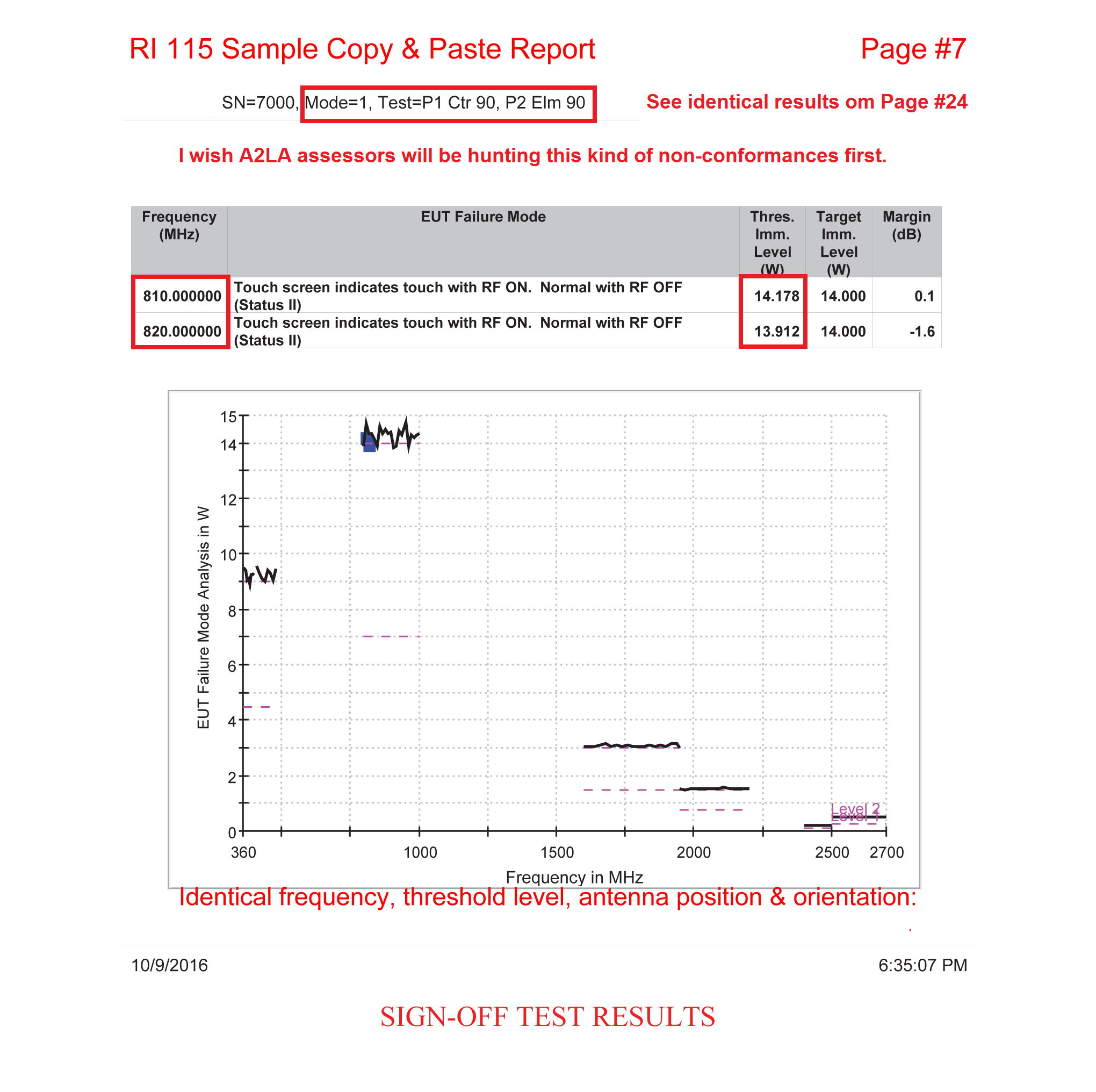
Page #7 vs Page #24

Looking over page's date/time the scan below was generated before the scan above. However the order of pages is as was listed in the full report.
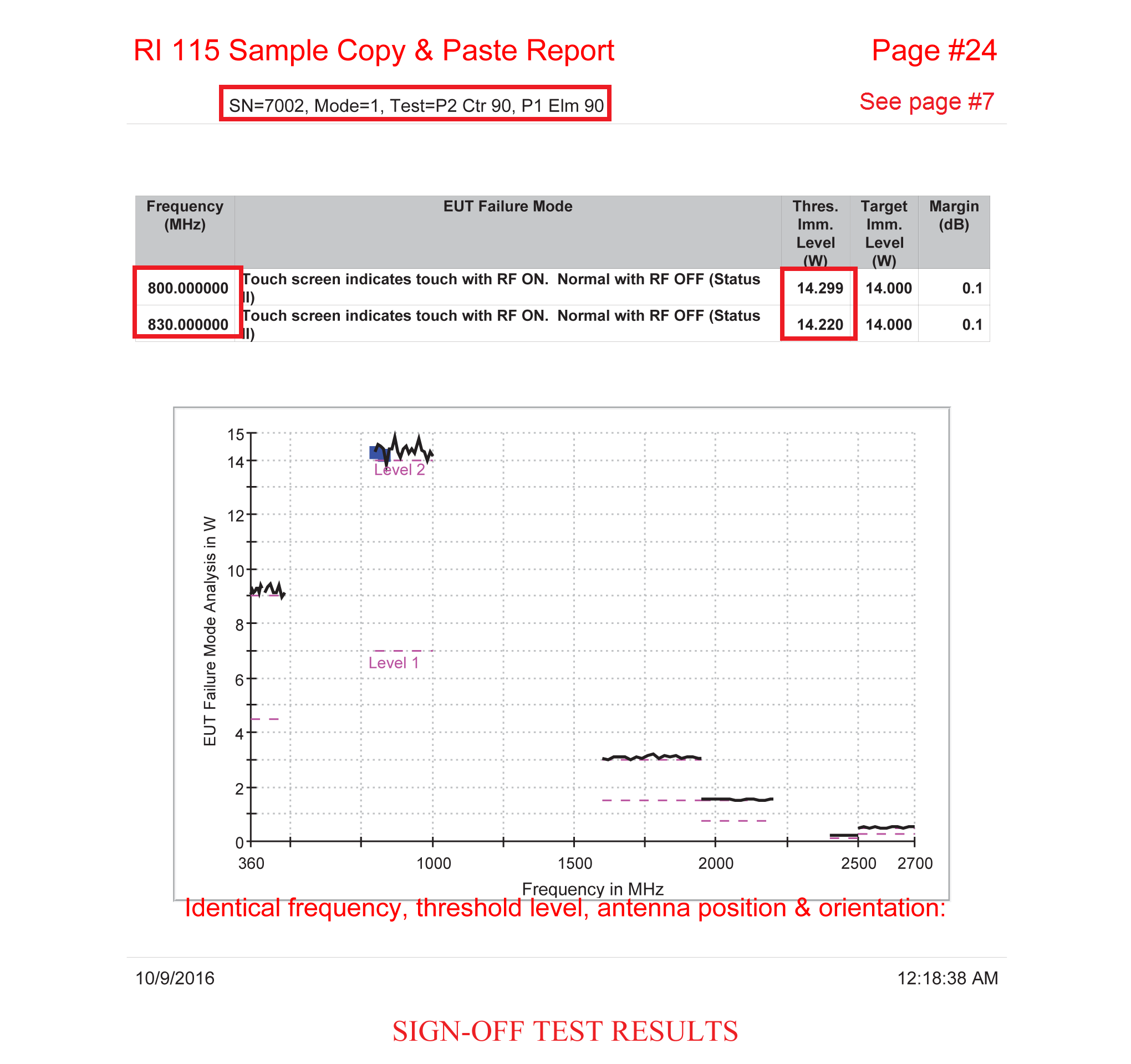
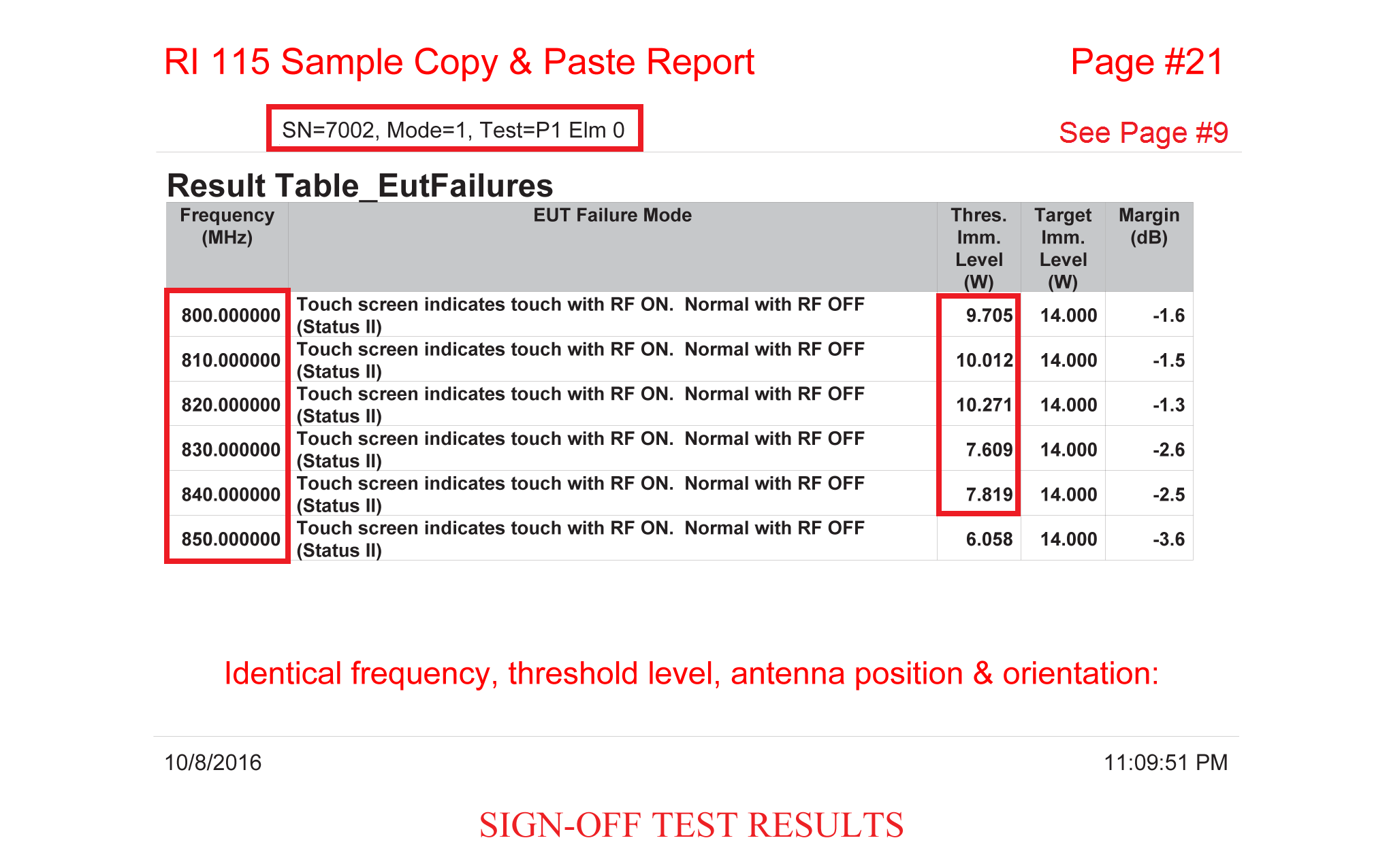
Page #9 vs Page #21
The test operator was in rush missing to change the test sample number from 7002 to 7000. Page #9 was supposed to show results from sample #7000. For the failed frequency step (850 MHz) the test operator slightly changed the Level 1 threshold value on the second tested sample (from 6.058 to 6.15 Watts) leaving unchanged the level 2 threshold values for all other  frequencies. Looking closely to date/time stamps they also are identical on both pages. Is this a honest mistake? 
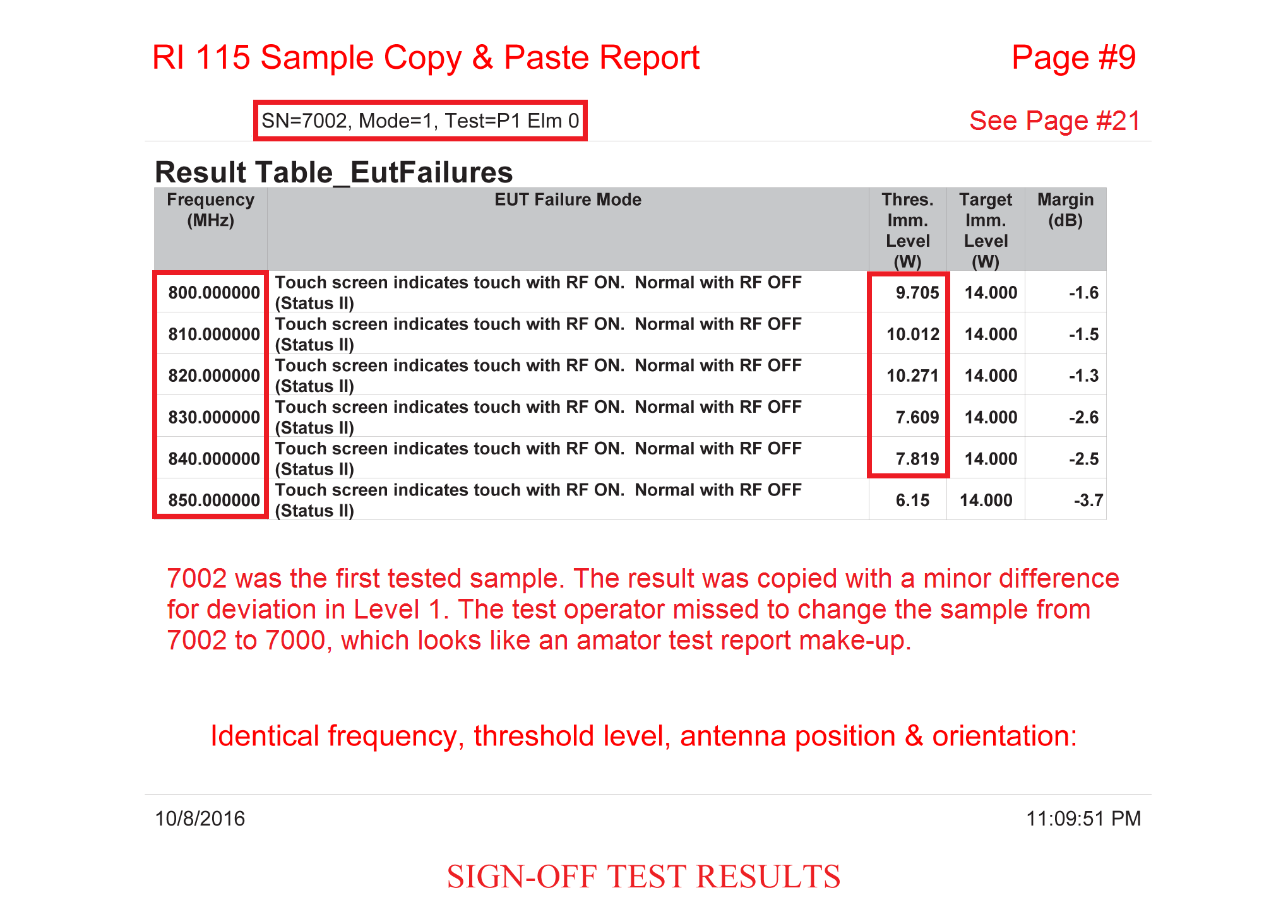
This kind of precision in measurements would humiliate any theory so far.
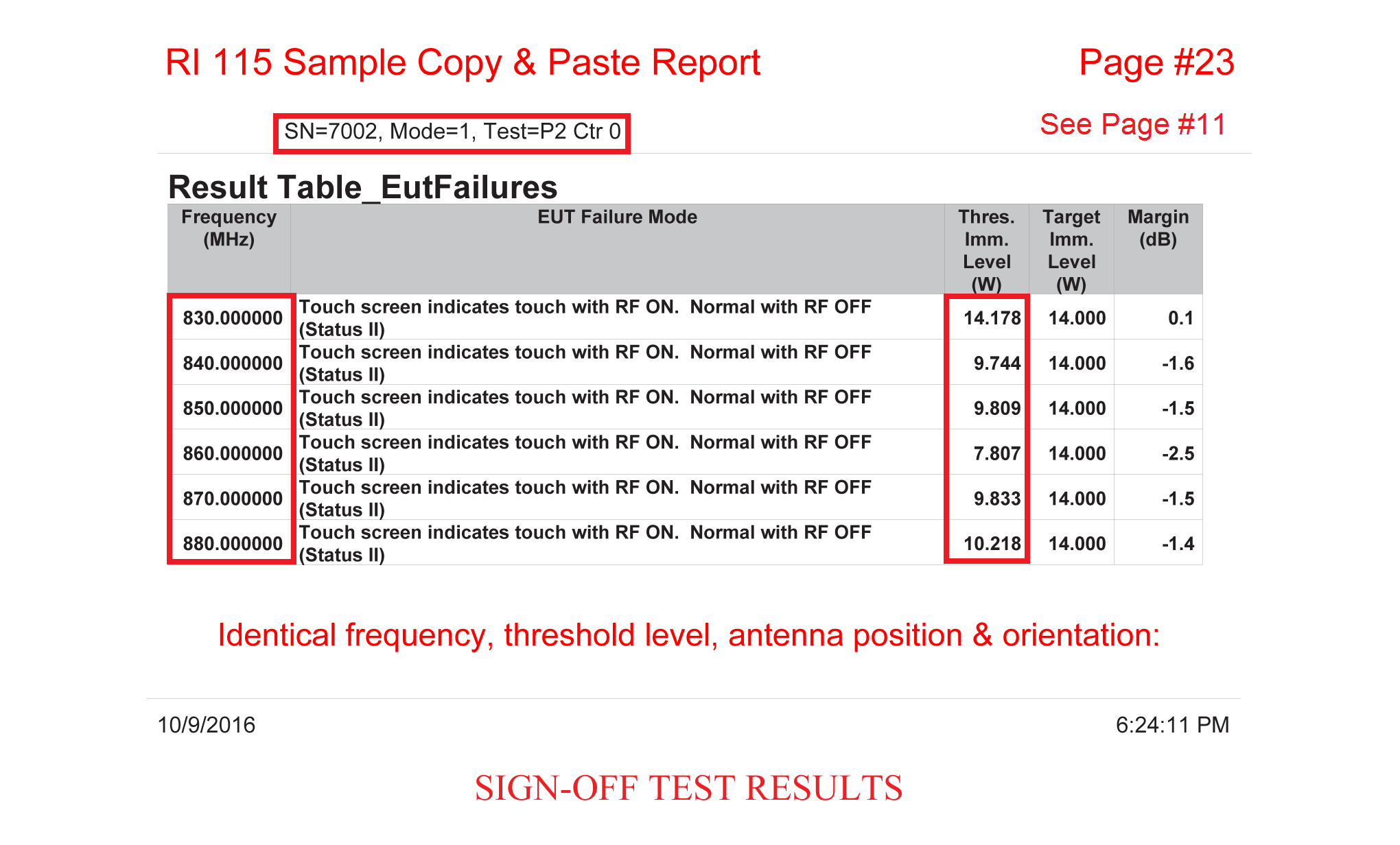
Page #11 vs Page #23

The perfect DUT type ever, perfect RI 115 equipment, perfect test operator, perfect identical hand portable transmitters immunity!
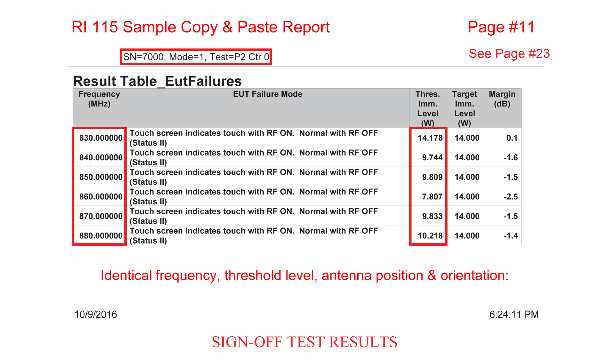
Going over pages's date/time they both have the same stamp. Theb why inserting them such that they apear to belong to separate test samples?
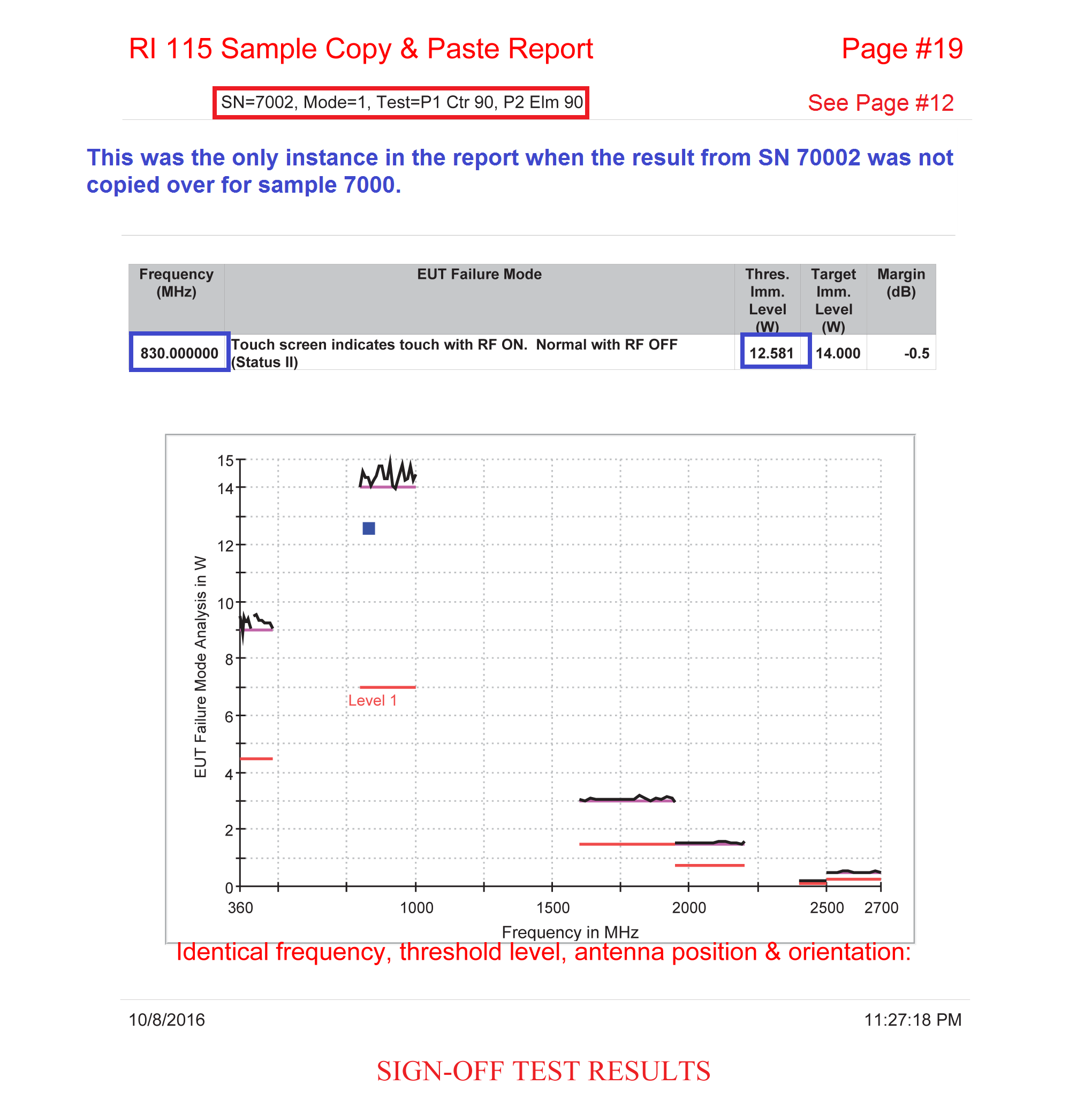
Page #12 vs Page #19

Surprisingly, but there is an antenna position where the result was either correctly tested or correctly represented.
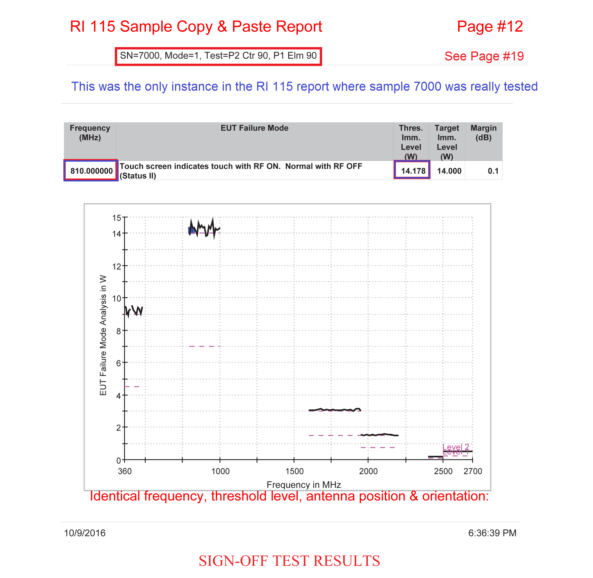
This was the only instance where the RI 115 result from one sample was not copied over the for the other sample.
Page #13 vs Page #25

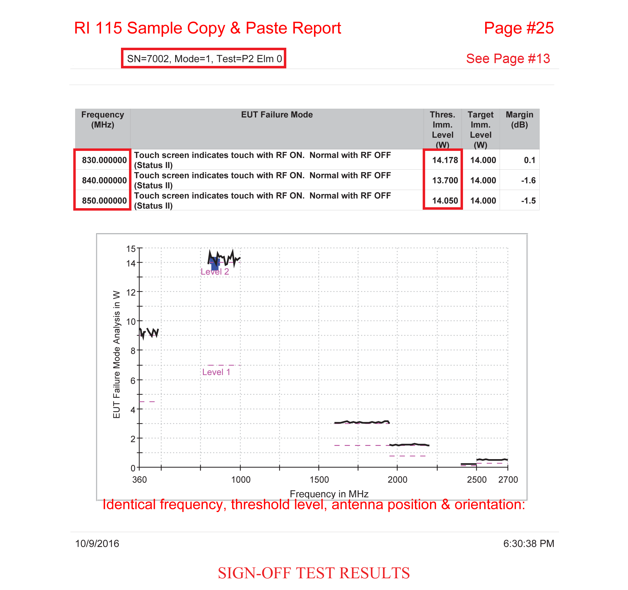
The RI 115 make up report saga continues. As long as the customer is preoccupied by the deviation in Level 1 it will never pay attention that only one sample was fully tested. The really bad part is that the designer will believe there is some sort of stability in DUT's behavior when in fact it was a huge instability.
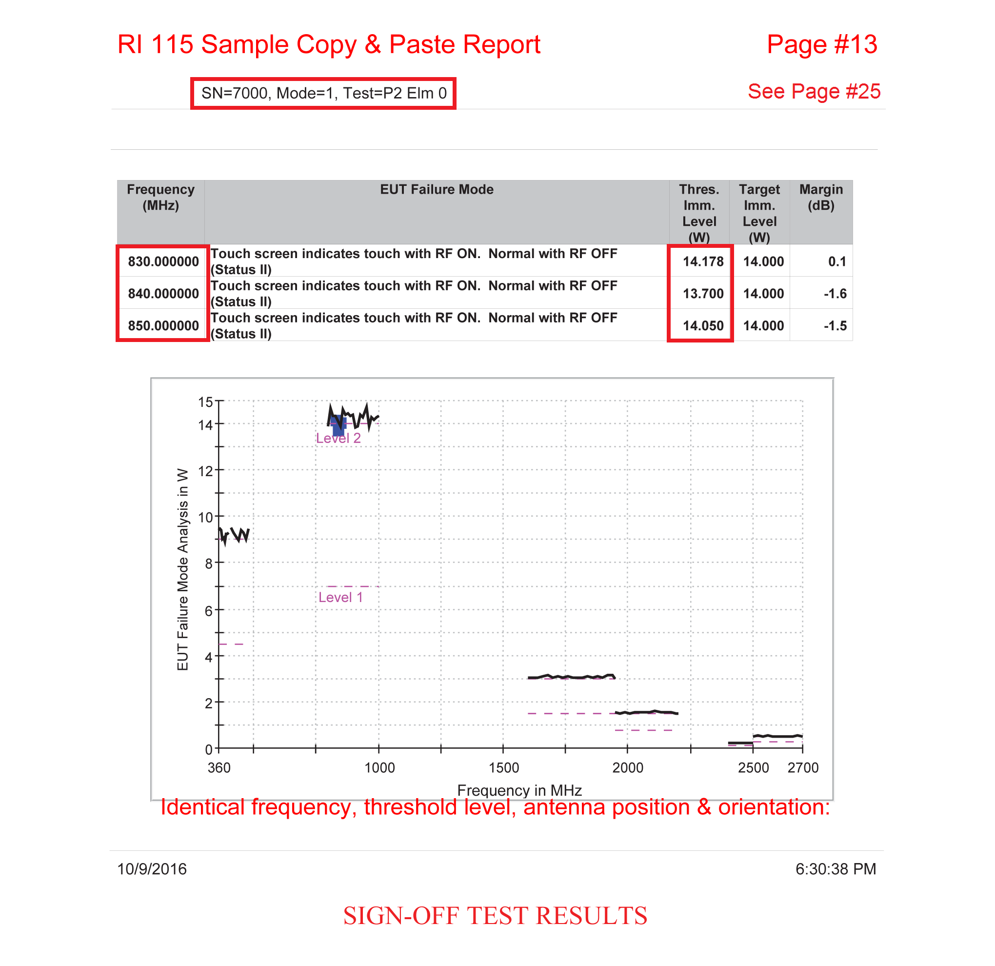
Again same date/time stamp but different test sample numbers. How was this possible?


Christian Rosu

Trialon EMC Laboratory, Burton, MI

Igor Klivak

EMC-CS-2009.1 CI 210 (Us Vp-p calibration issue)

17. April 2017 15:30 by Christian in
ES-XW7T-1A278-AC Immunity from Continuous Disturbances: CI 210This test refers to continuous di

ES-XW7T-1A278-AC Immunity from Continuous Disturbances: CI 210

This test refers to continuous disturbances produced by vehicle’s charging system that can affect DUT functions.


FMC1278 Rev2 vs EMC-CS-2009.1 - CI 210 Requirements

  • Level 2 requirements, as delineated in ES-XW7T-1A278-AC was removed in EMC-CS-2009.1, then added back in FMC1278.
  • The frequency range allocated for severity levels was changed subsequently in all three Ford EMC specifications.
  • The most significant differences for Us Vp-p requirements occurred between  ES-XW7T-1A278-AC & EMC-CS-2009.1.


CI 210 Frequency Steps

The most significant differences in frequency steps requirements occurred between  ES-XW7T-1A278-AC & EMC-CS-2009.1.


ES-XW7T-1A278-AC CI 210: Test Setup
  • The test harness connecting the DUT to the Test Fixture and transient pulse generator shall be < 2000 mm in length.
  • The DUT and wire harness shall be placed on an insulated support 50 mm above the ground plane. If the outer case of the DUT is metal and can be grounded when installed in the vehicle, the DUT shall be mounted and electrically connected to the ground plane.

ES-XW7T-1A278-AC CI 210: Test Procedure

  1. Adjust DC offset of the signal generator/audio amplifier to 13.5 volts with the DUT disconnected (open circuit)
  2. At each test frequency set and record the signal generator output to the specified voltage level with the DUT disconnected (open circuit).
  3. Without the test signal present, connect the DUT and verify that it is functioning correctly.
  4. Apply the test signal to the DUT and the Test Fixture such that all power and control circuits are exposed to the disturbance. All power and control circuits are tested simultaneously.
EMC-CS-2009.1 CI 210: Test Setup

  • The test harness connecting the DUT to the Load Simulator and modulated DC supply shall be < 2000 mm in length.
  • All DUT power/power return circuits shall be connected together at the modulated power supply.
  • Per previous versions of this requirement, a ground plane may be placed under the DUT and Load Simulator, but if used, the DUT and wire harness shall be placed on an insulated support 50mm above the ground  plane. Additionally, the negative connection of the modulated DC supply and case of the Load Simulator shall be referenced to the ground plane.


EMC-CS-2009.1 CI 210: Test Procedure

  1. Without the DUT connected, adjust the DC voltage offset "Up" of the modulated power supply to 13.5 volts. Initially set the AC voltage amplitude "Us" to zero volts.
  2. Connect and activate the DUT and verify it is functioning correctly. Verify that Up remains at 13.5 VDC. Adjust the supply as required to achieve this voltage level.
  3. At each test frequency increase Us to the corresponding stress level while the DUT is operating. The dwell time shall be at least 2 seconds. A longer dwell time may be necessary if DUT function response times are expected to be longer. This information shall be documented in the EMC test plan.
FMC1278 CI 210: Test Setup

  • The test harness connecting the DUT to the Load Simulator and modulated DC supply shall be < 2000 mm in length.
  • All DUT power/power return circuits shall be connected together at the modulated power supply.


FMC1278 CI 210: Test Procedure

  1. Without the DUT connected, adjust the DC voltage offset "Up" of the modulated power supply to DUT’s system voltage (13.5, 27 volts). “Us” is initially set to zero volts.
  2. At each test frequency adjust and record the signal generator output required to achieve the specified modulation voltage level “Us” with the DUT disconnected (open circuit). Use the frequency steps listed.
  3. Without the modulation signal present (i.e. Us = 0 volts), connect the DUT and verify it is functioning correctly.
  4. At each test frequency, apply the signal generator levels recorded in step (2) to the DUT and the Load Simulator such that all power and control circuits are exposed to the disturbance. The dwell time shall be at least 2 seconds. A longer dwell time may be necessary if DUT function response times are expected to be longer. This information shall be documented in the EMC test plan and test report.
Fixing EMC-CS-2009.1 CI 210 Us (Vp-p) calibration issue:

CI 210 test waveform is not the superimposed alternating voltage per ISO 16750-2. 
Prior to test Us is calibrated (substitution method) to maintain the required Us V(p-p) while DUT is driving high current loads (e.g. 30A): at each test frequency increase Us to the corresponding stress level while the DUT is operating. The amplifier (e.g. Techron 7796) is configured to operate as Voltage-Controlled Source. Whenever functions are paused between activations (very low current) the amplifier will increase its output voltage in an attempt to drive the requested current into DUT as recorded during Us (Vp-p) calibration. This will result in high voltage (e.g. above 40V) being present for long enough time at DUT VBATT input that can damage components.

The solution is to run CI 210 per FMC1278 that has corrected the test procedure: at each test frequency adjust and record the signal generator output required to achieve the specified modulation voltage level “Us” with the DUT disconnected (open circuit).


Christin Rosu