EMC FLEX BLOG A site dedicated to Automotive EMC Testing for Electronic Modules

ANTENNA TYPE

16. December 2020 06:35 by Christian in EMC/EMI, Troubleshooting, Test Equipment
ANTENNA TYPE FREQUENCY RANGE USAGE NOTES LOOP 1 KHz TO 30 MHz Magnetic Field 20 dB dynamic range f
ANTENNAFREQ. RANGEUSAGENOTES
LOOP1 KHz TO 30 MHzMagnetic Field20 dB dynamic range for 1 KHz
ROD1 KHz TO 30 MHzRadiated Emissions41 inches long, uses ground plane and active amplifier
BICONICAL20 MHz to 200 MHzRadiated EmissionsRequired by automotive standards
DIPOLE100 MHz to 1 GHzShielding Effectivenessmore efficient above 400 MHz 
LOG PERIODIC200 MHz to 1 GHzRadiated EmissionsCISPR 25
BICONLOG20 MHz to 1 GHzRadiated EmissionsEuropeean requirements
LOG SPIRAL200 MHz to 10 GHz Shielding EffectivenessCone-shaped. Can't distiguish between horizontal and vertical polarization
HORNabove 1 GHzRE, RI ALSEHighly efficient, directional, can be harmful causing blindness, glaucoma
RIDGED HORN1 GHz to 10 GHzRI ALSEBroadband
HOOD RI ALSEHorn antenna with a metallic hood around it for safety.
HAND-HELD Shielding Effectiveness 
DISCONE  Shielding Effectivenessnot directional
YAGIbelow 100 MHz Shielding Effectiveness 

One-Meter Horizontal Distance Antenna to DUT Radiated Emissions Measurements

The horizontal distance between DUT and Antenna for automotive EMC compliance is 1 meter. For other

The horizontal distance between DUT and Antenna for automotive EMC compliance is 1 meter. For other non-automotive regulatory and standard-based measurements these distances are 3m, 10m, or 30m.

One-meter DUT-to-antenna distance measurements are carried out based on MIL-STD 461 (military), RTCA DO-160 & EUROCAE ED-14 (commercial aircraft), and CISPR 25 (automotive).

CISPR 25 specifies a one-meter antenna distance to be used for radiated emissions from Components/Modules in an Absorber Lined Shielded Enclosure (ALSE).


The near field and far field are regions of the electromagnetic field (EM) around an object.
Far-field E (electric) and B (magnetic) field strength decreases as the distance from the source increases, resulting in an inverse-square law for the radiated power intensity of electromagnetic radiation.

Near-field E (electric) and B (magnetic) field strength decrease more rapidly with distance:

  • the radiative field decreases by the inverse-distance squared, resulting in a diminished power in the parts of the electric field by an inverse fourth-power
  • the reactive field by an inverse cubed law, resulting in a diminished power in the parts of the electric field by an inverse sixth-power

The rapid drop in power contained in the near-field ensures that effects due to the near-field essentially vanish a few wavelengths away from the radiating part of the antenna.

dF = (2* D^2)/λ
D= largest dimension of the radiator or diameter of antenna
λ = wavelength of the radio wave
dF = 2*(D/λ)^2
λ = 2* (D/λ)*D
dF >> D
dF >> λ

Near-field and far-field regions for an antenna (diameter or length D) larger than  the wavelength of the radiation it emits, so that ​D⁄λ ≫ 1:

  • Near Field
    R = near field antenna to radiating filed distance
    R = 0.62 * (D^3/λ)^1/2
  • Far Field
    Ro = far field antenna to radiating filed distance
    Ro = 2*(D^2/ λ)


CISPR-25 RE per CS.00054:2018

15. October 2019 10:00 by Christian in EMC/EMI, OEM Specs, Test Equipment, Test Methods
CISPR-25 Generic Test Setup for compliance to CS.00054:2018.

CISPR-25 Generic Test Setup for compliance to CS.00054:2018

CS.00054 Radiated Emissions Block Diagram
 
The vertical monopole element is centered at 1m from the center of the 1.7m test harness. Note that 1.5m of the harness is running at 10 cm parallel with ground plane edge. The antenna counterpoise is placed +10/-20 mm vs GP. 
 
CISPR-25 Generic DUT Setup. The DUT is placed @ 20 cm from the edge of GP. The 1.7 m Test Harness is routed 90 degrees towards DUT.
 
The ground plane is connected to chamber's floor to a dedicated Earth Grounding Rod.
 
LISN (700 V DC / 500 A) & Load Simulator side of the test setup. 
DUT's B+ & GND lines are connected to LISN's outputs.
 
THE BICONICAL ANTENNA IN VERTICAL POLARIZATION. 
The antenna is centered on the 1.5m harness running at 10 cm parallel with GP edge.
 
THE BICONICAL ANTENNA IN HORIZONTAL POLARIZATION. 
The antenna is centered on the 1.5m harness running at 10 cm parallel with GP edge.
 
THE LOG PERIODIC ANTENNA IN VERTICAL POLARIZATION. 
The tip of antenna is 1 m away from the center of the test harness.
 
THE LOG PERIODIC ANTENNA IN HORIZONTAL POLARIZATION. 
The tip of antenna is 1 m away from the center of the test harness.
 
Octave Antenna Vertical Polarization with its aperture centered on DUT at 1 m distance from test harness.
 
Octave Antenna Horizontal Polarization with its aperture centered on DUT at 1 m distance from test harness.
 
Horn Antenna Horizontal Polarization with its aperture centered on DUT at 1 m distance from test harness.
 
Horn Antenna Vertical Polarization with its aperture centered on DUT at 1 m distance from test harness.


3-METER ALSE CHAMBER & Equipment Control Shielded Room.
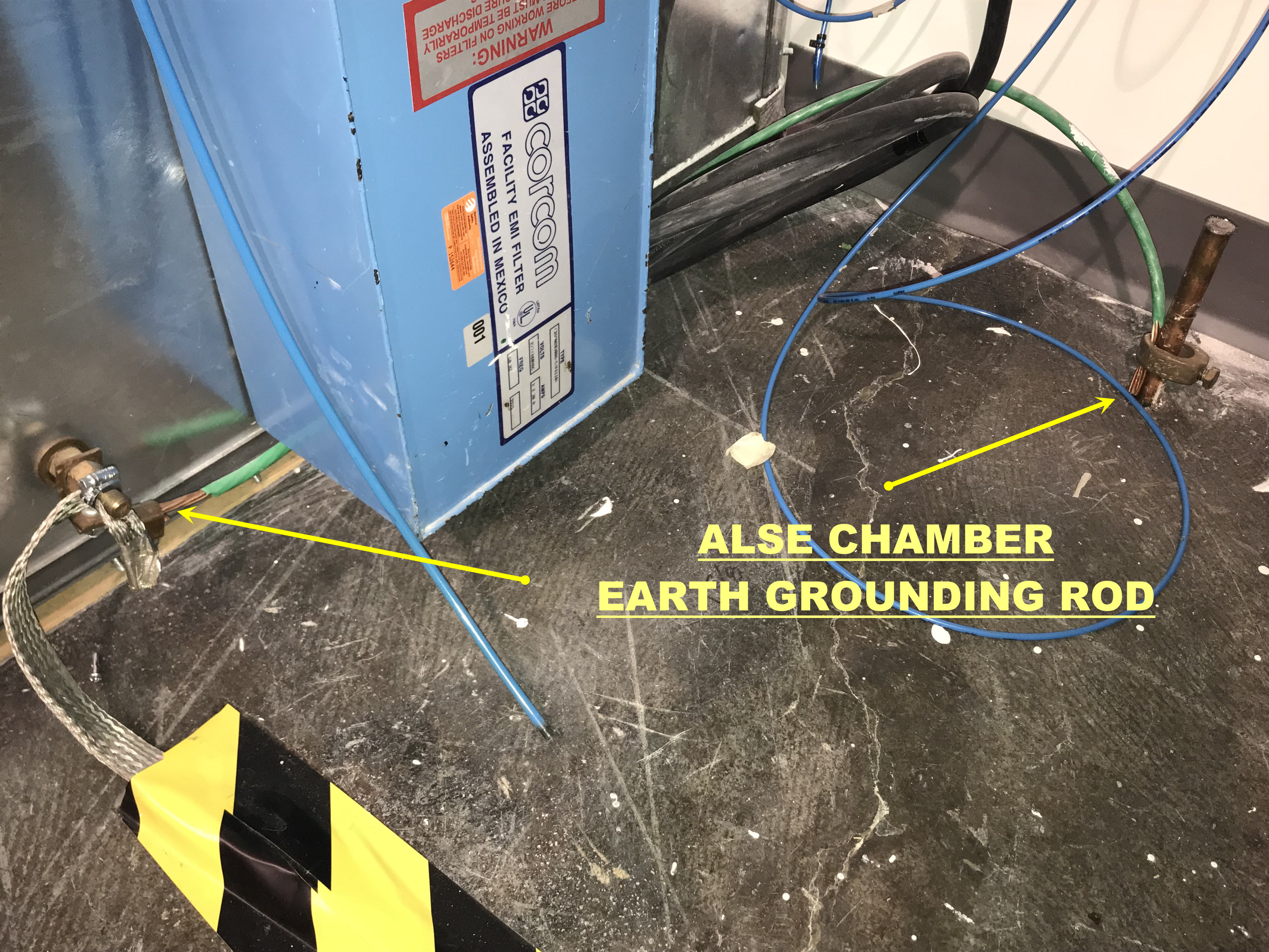
 

ALSE CHAMBER EARTH GROUNDING ROD.

LISN (Line Impedance Stabilization Network) or AN (Artificial Network)

14. September 2015 14:29 by Christian in EMC/EMI, Standards, Test Equipment
Purpose of the LISN:1. Provide well defined RF impedance to the DUT.2. The 1μF & 50μH filt

Purpose of the LISN:
1. Provide well defined RF impedance to the DUT.
2. The 1μF & 50μH filter isolates the noise that is put on the supply lines by DUT from feeding back to the power supply / battery.
3. Provide a low impedance path for the noise to be measured at the output port of the LISN coupling the interference voltage generated by DUT via 0.1μF to the analyzer or receiver.

The role of the LISN is to isolate the DM current and CM current from the power supply, and to minimize the impact of the CM current by returning it to its sources.

The wire harness inductance for large systems (aircraft) is 50μH whereas for small systems (automotive) is 5μH. However, the LISN selection criteria should be based on the frequencies of the measurements required.


Types of LISN

  1. V-LISN: Unsymmetrical emissions (line-to-ground)
  2. Delta-LISN: Symmetric emissions (line-to-line)
  3. T-LISN: Asymmetric emissions (mid point line-to-line)


There are two types of V-LISN with different impedances.

  • 5 µH inductance (CISPR 16-1-2, CISPR 25, ISO 7637, SAE J1113-41, DO160) are normally used to measure equipment for vehicles, boats and aircrafts connected to on-boards mains with DC or 400 Hz.
  • 50 µH according to CISPR 16-1-2, MIL STD 461 and ANSI C63.4 is intended to operate at mains frequencies of 50 Hz or 60 Hz.

The T-LISN measures the asymmetric disturbance voltage (common mode voltage) and provides it to an EMI Receiver. It is normally used for measuring telecommunication and data transmission equipment connected to symmetrical lines as e.g. twisted pairs.

CISPR-25 (Ed 3.0)
A network inserted in the supply lead or signal/load lead of apparatus to be tested which provides, in a given frequency range, a specified load impedance for the measurement of disturbance voltages and which may isolate the apparatus from the supply or signal sources/loads in that frequency range.
CISPR-25 (Ed 3.0) & ISO-11452-2:2004 & ISO-11452-4
The AN impedance ZPB (tolerance ± 20 %) in the measurement frequency range of 0.1 MHz to 100 MHz it is measured between the terminals P and B with a 50 Ω load on the measurement port and with terminals A and B short-circuited.


The 1μF capacitor is populated in CISPR-25 LISN; R=1Kohm.


ISO 7637-2:2011 & ISO-11452-2:2004 & ISO 7637-2:2004
The artificial network is used as a reference standard in the laboratory in place of the impedance of the vehicle wiring harness in order to determine the behavior of electrical/electronic devices.
ISO 7637-2:2011 & ISO 7637-2:2004
The resulting values of impedance ZPB, measured between the terminals P and B while terminals A and B are short-circuited, are given in figure below as a function of frequency assuming ideal electric components. In reality, the impedance of an artificial network shall not deviate more than 10 % from the given curve.


No 1μF populated in ISO 7637-2 LISN; R =50 ohm, C is function of voltage.


Sample setup: CISPR-25 require separate LISN for B+ and GND lines.

Christian Rosu