ISO 7637-2 Pulse 1
Conducted Immunity to Transients on battery lines.
Pulse 1 (Us = -150V, Ri = 10Ω, td = 2 ms, tr = 1µs, t1 = ≥ 0.5s (repetition rate), t2 = 200 ms, t3 < 100µs) can upset functionality of electronic modules. Most automotive OEM specs are accepting Class B response (DUT self-recoverable deviations), others are asking Class A response (no deviations) during Pulse 1.
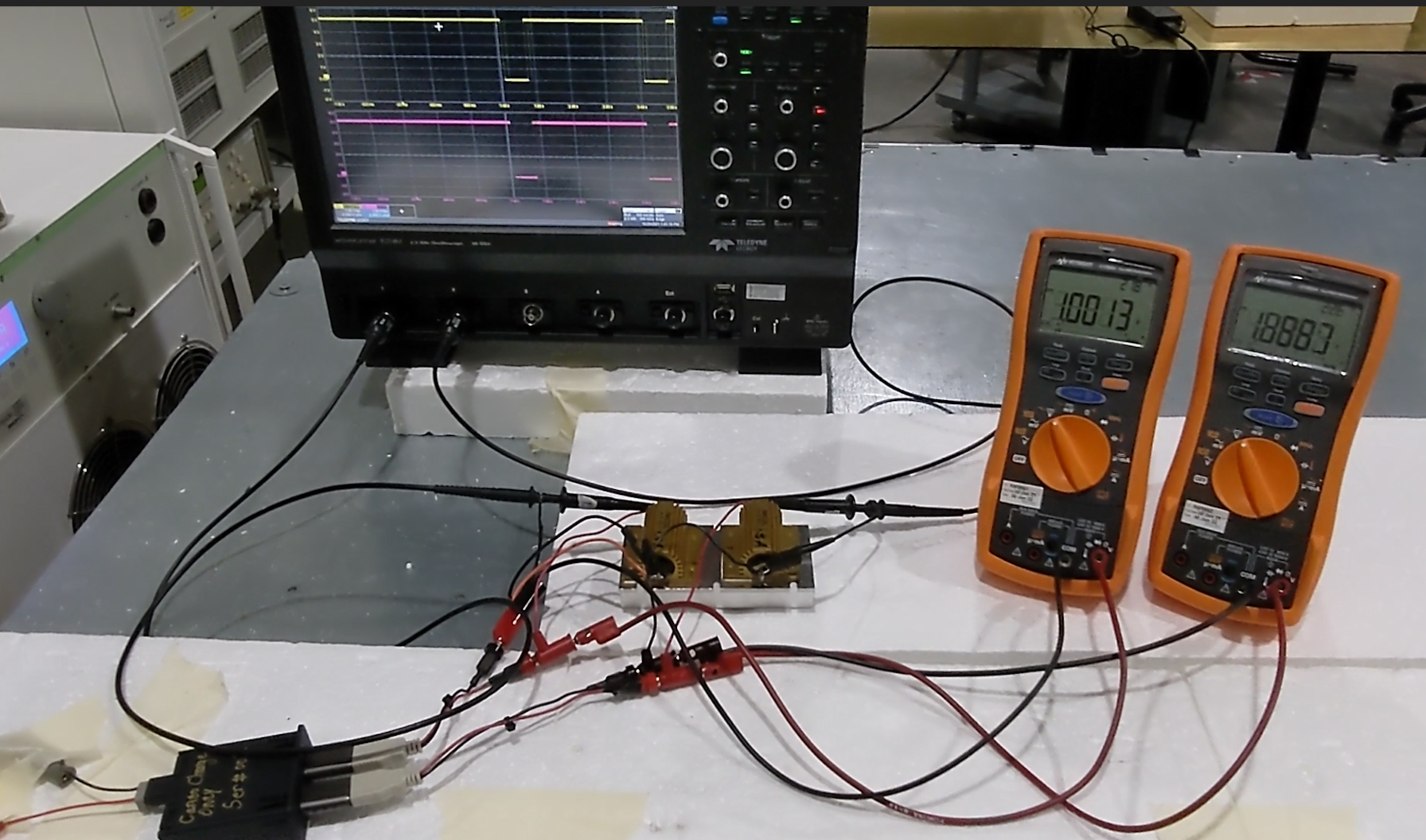
In this particular case the pass/fail criteria was Charging Voltage remains 5V ±0.5V for 12V Battery dropouts ≤ 500µs. The EMC test plan asked the use of DMM to monitor the USB charging function for a Class A expected response:
- This was a simulation of a mobile phone charging event.
- DMM can only detect 5V Charging Voltage dips/drops ≥ 250 µs. A FLUKE can be set to count MAX and MIN voltage peaks, otherwise to monitor 5V fast voltage fluctuations is not practically possible.
- The EMC test plan allowed the use of oscilloscope only for information.
Download this movie to see how the charging function was monitored simultaneously on both oscilloscope and DMM:
5V_Charging_during_P1.mp4 (127.57 mb)
A similar monitoring equipment limitation was imposed the EMC Test Plan for dropouts test. Download this movie to see how the charging function was monitored simultaneously on both oscilloscope and DMM:
5V_Charging_during_500_microSec_dropout.mp4 (30.91 mb)
Christian Rosu, Nov 8, 2021
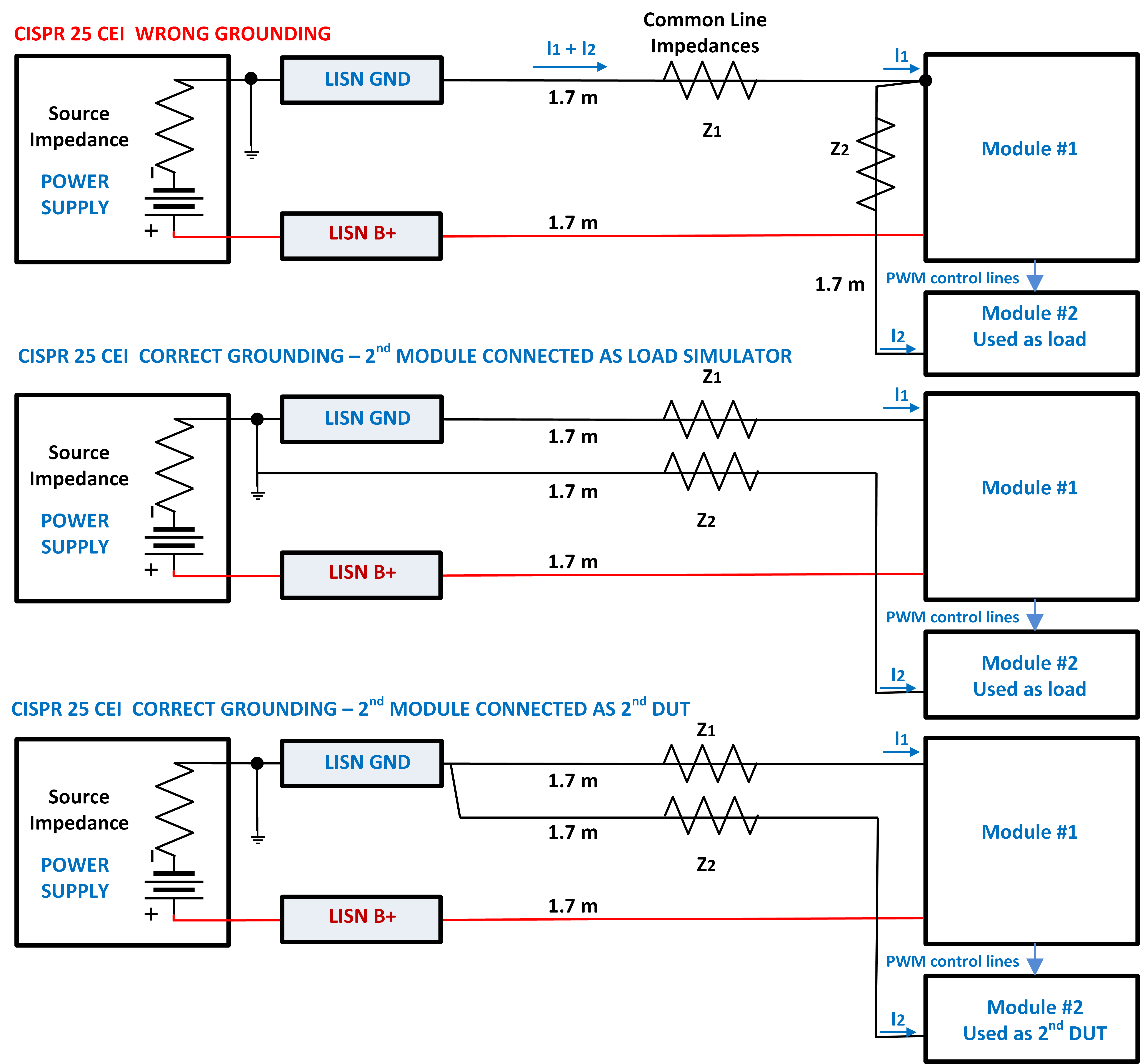
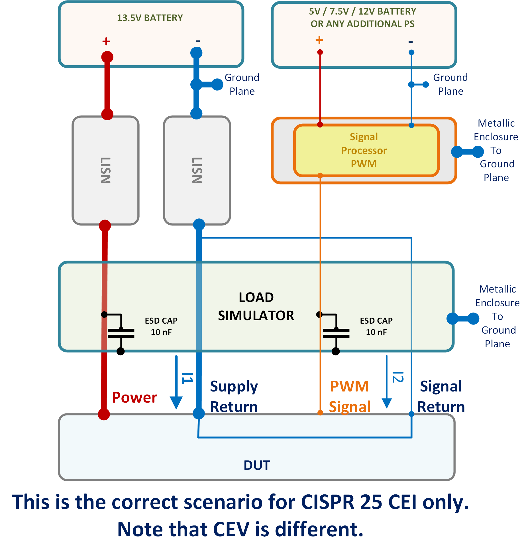
An incorrect DUT grounding scheme can easily make the difference between compliance and non-compliance to CISPR 25 CEI limits. Sometimes we have to evaluate CEI from two modules, one used as DUT and the other one used as DUT's load (e.g. Module #1 is a PWM maker while Module #2 is an LEDs Lamp).
Christian Rosu, 2021-06-09
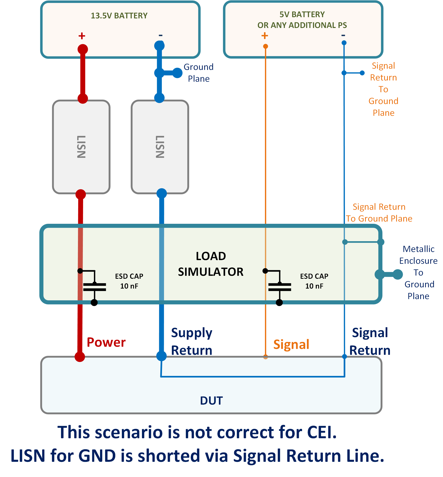
A few remarks on correct Load Simulator configuration for CISPR 25 Conducted Emissions Current test method.
First of all you have to show the LISN in your EMC Test Plan block diagrams. The way the LS is connected is not identical for each CISPR 25 test method. I will never use a Load Simulator unless is no other way around or I would want to turn it into a RF filter box. Examples of CEI good and bad setups are shown below:
CEI WRONG CONFIGURATION
CEI GOOD CONFIGURATION
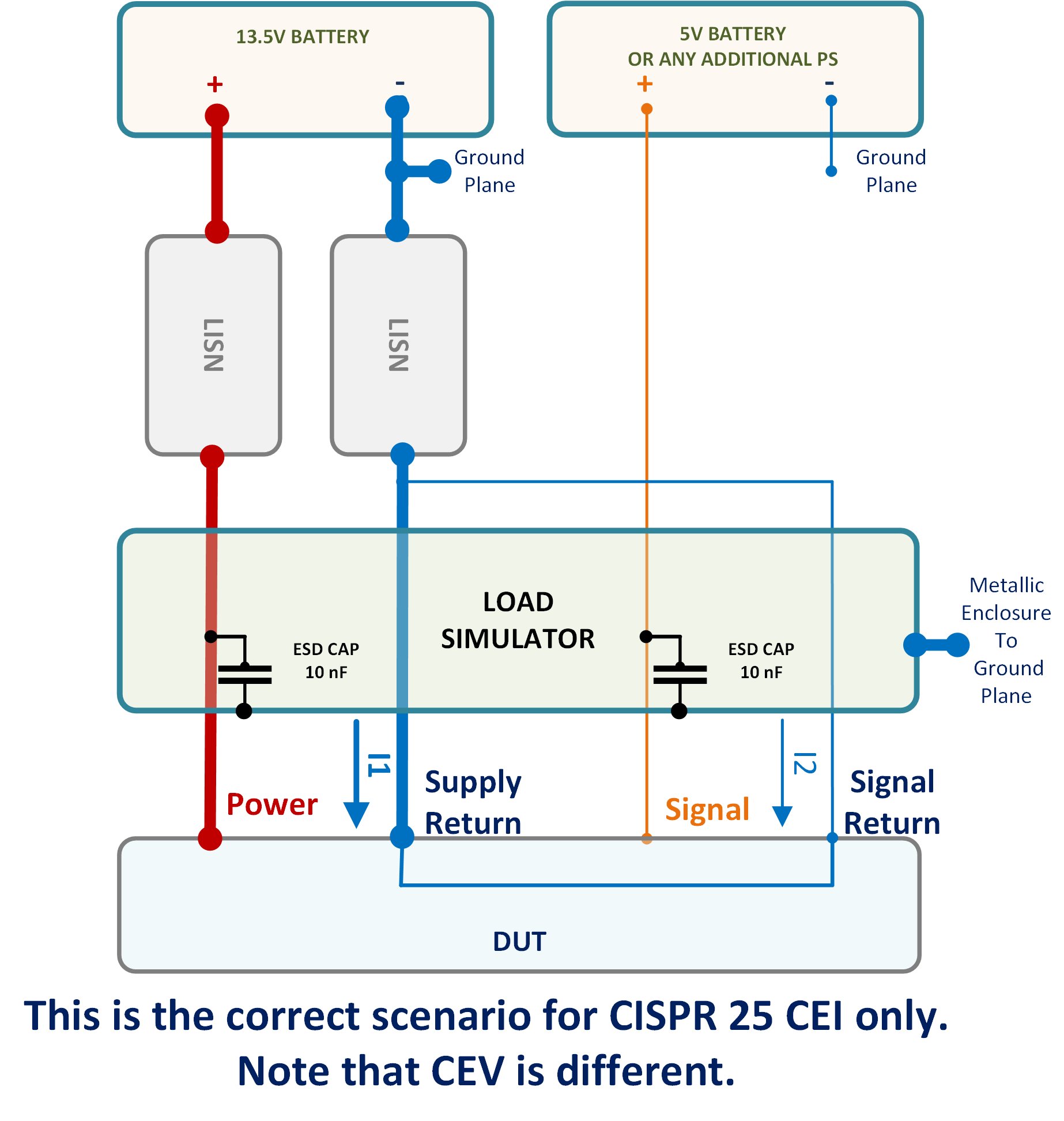
To clarify how a PWM maker is connected:
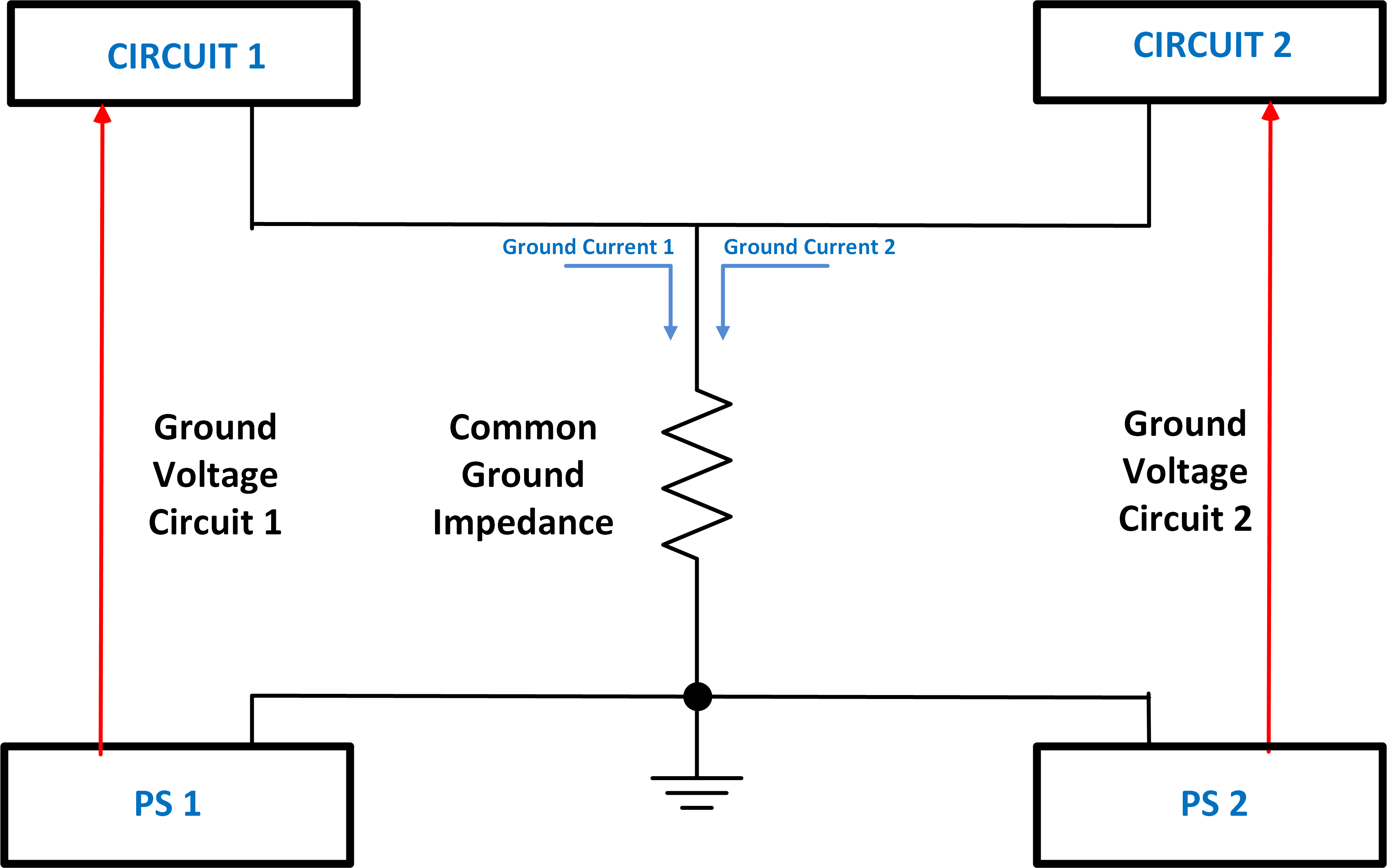
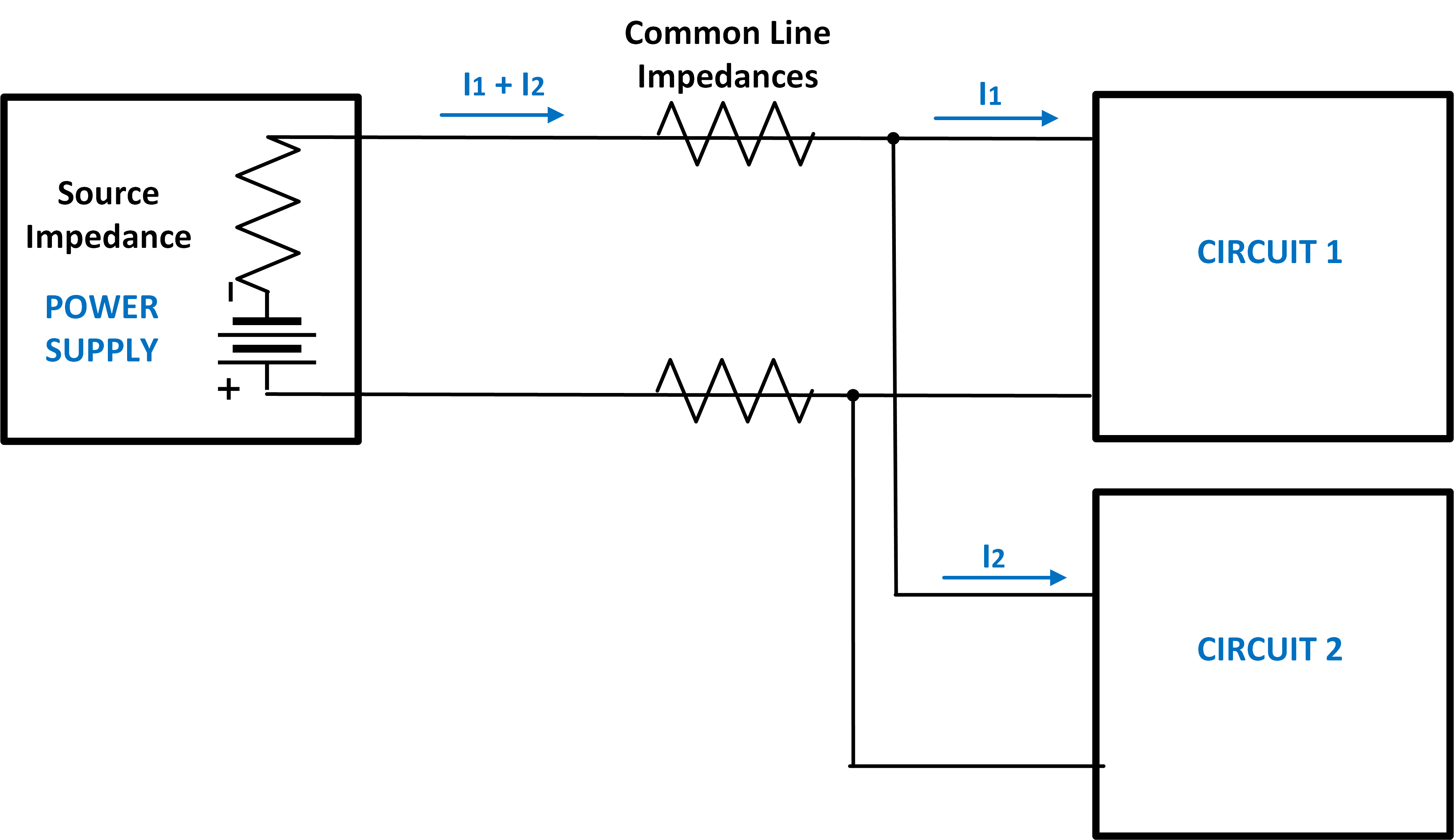
From EMC compliance perspective the goal is to avoid as much as possible common line impedances:
Christian Rosu
2021-04-13
In EMC "dropout" means Battery drops to 0V. FMC1278R3 (CI 260) is an example of various combinations of such battery voltage dropouts. The problem is that no automotive battery can really drop its output to 0V for say 5 seconds as well as for 50 ms without to blowout a fuse.
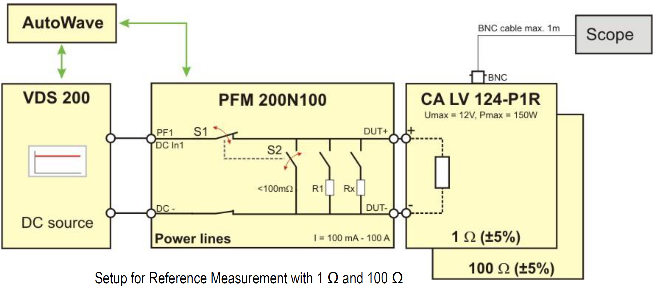
Therefore the only way to simulate correctly a “battery drop to 0V” is to disconnect DUT's B+ line from battery. The test equipment offers such capability to momentarily disconnect the battery during “voltage dropout” simulating a “0V” like condition, practically no current through supply lines to DUT.
This involves the use of PFM200N + VDS200Q + AutoWave to generate the CI 260 type of pulses. PFM200N acts like a very fast switcher disconnecting its output from DUT. So far only FCA (CS.00054) figure it out to ask “open condition” during “0V” battery voltage dropouts.
In EMC we use the wording “voltage dip” to describe a momentary battery voltage drop (e.g. 4.5V) below minimum supply voltage (e.g. 9V). Obviously in this scenario the Battery B+ line is not disconnected from DUT during the “voltage dip to 4.5V” of 100ms.
Christian Rosu Feb 17, 2021
The DUT Performance Functional Verification is based on a bench test software that does not account for EMC specific considerations and is normally performed prior and following each EMC test method.
Using the same Activation & Monitoring Method and Pass/Fail Criteria for ENV and EMC is not practical. DUT’s functions must be grouped in “operating modes” that are in line with the scope of EMC Test Method. When assessing the level of RF emissions we want the DUT to exhibit the highest level of noise possible as in vehicle. During RF Immunity evaluation we expect the following from a good activation/monitoring software:
- Capability to activate and have realistic data traffic on all I/O lines as well as individual I/O lines.
- Electrical Transients or RF coupled in supply voltage and I/O lines may not always trigger repeatable anomalies. Therefore we need a visible flag/indicator to immediately stop the actual EMC test method process for anomaly thresholding (e.g. level vs frequency). As we reduce applied stress level the DUT’s behavior may change, then at some point the anomaly should disappear.
- The same DUT operating mode may be feasible for one or more EMC test methods but definitely not for the entire test list. We need capability to configure what functions belong to each operating mode including live monitoring method. Log files are not useful during test, we still need them following the test for troublesooting.
- All functions must resemble vehicle intent usage. Not all I/O lines will be active simultaneously in vehicle. Therefore do not use unrealistic I/O cables scenarios to facilitate testing since this can generate false current loops and other issues.
- The functions used by DUT activation & Monitoring Software are not meant to assess complaince to USB, E-Net, LVDS standards.
Keep in your mind that:
- Electrical Transients on supply lines can hard reset the MCU (e.g. dips/dropouts). Is there a test in your monitoring software that captures such condition? Any other anomaly is not relevant once a hard reset occurs.
- Do you have a function to verify that there is no memory loss following inadvertent hard/soft reset?
- The RF can be coupled in both supply lines and I/O lines resulting in data traffic interruptions leading to a soft reset. Is there a monitoring function to capture such event?
- If CAN bus is used in a design I would consider at minimum two critical errors: CAN BUSOFF & DTC SET. What we normally use is a pass fail criteria that can be adjusted such that is possible to determine if the anomaly occurs with every data transmission attempt or it happens only each 100/1000 attempts.
DUT support software
Do not waste time/money to tweak operating modes during EMC validations. In many EMC labs the cost for one hour of ALSE chamber is $500 regardless to how you spend this time. The operating mode must be pre-selected, yet adjustable if needed during troubleshooting. The "anomaly found" visual indicator is used by EMC test operator to stop the actual EMC test software. If we have a time stamp in log files, there is no need to stop the activation/monitoring support software.
DUT Activation Dwell Time
All functions within the same operating mode must be completed and repeated every 2 seconds. We call these 2 seconds Dwell Time, and it can make a huge difference in test duration and cost. For a 2-second dwell time and only one Operating Mode you can expect RF Immunity in ALSE chamber to last 4-5 days (one shift). For a 4-second dwell time it may last practically 8-9 days and so on. Bottom line, if the initialization of Load Simulator or DUT is time consuming it will cost a fortune to re-initialize following each incident/anomaly. Hard/soft reset must always be the last resort to resume operation. The goal is to minimize the number of operating modes and DUT orientations.
Types of DUT support software
- Load Simulator EMC support testing software with specific sections for each Operating Mode.
- Load Simulator Functional/Parametric verification testing done before and after each Test Method.
- Full DUT Functional/Parametric testing before and after full EMC validation that is not typically done using the EMC Load Simulator but rather EOL like testers.
DUT Operating Mode
Ideally is to include in Operating Modes only those DUT functions that are active while driving the vehicle. Functions used for diagnostics at the car dealer shop are not relevant. The worst case scenario is when vehicle is in Run Mode (speed >0) but we also have to simulate the Standby Mode (speed = 0) and Sleep Mode (current consumption < 1 mA).
Christian Rosu, Jan 12, 2021