Near-field interference (crosstalk) is a major issue in electronic devices and systems when comes to EMC compliance. To reduce crosstalk, as well as far-field interference, the transmission lines can be shielded. The length of transmission lines and spacing between the conductors should be as small as possible. The steel tube around the untwisted pair is superior to both the aluminum and copper tube due to its magnetic properties.
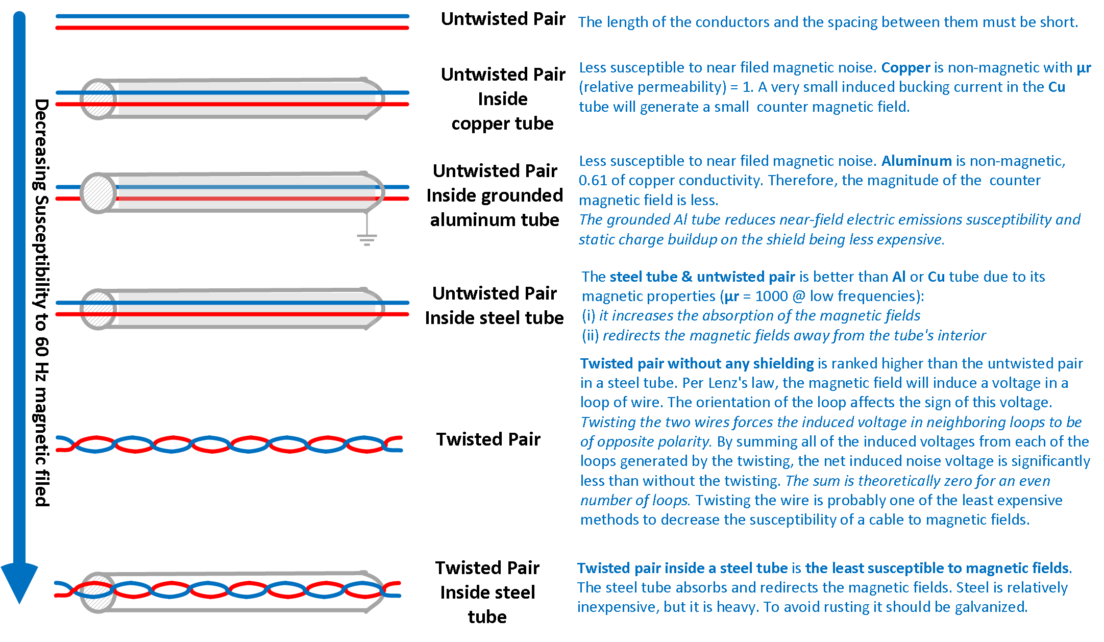
Untwisted Pair
The length of the conductors and the spacing between them must be short.
Untwisted Pair Inside Copper Tube
Less susceptible to near filed magnetic noise. Copper is non-magnetic with μr (relative permeability) = 1. A very small induced bucking current in the Cu tube will generate a small counter magnetic field.
Untwisted Pair Inside Grounded Aluminum Tube
Less susceptible to near filed magnetic noise. Aluminum is non-magnetic, 0.61 of copper conductivity. Therefore, the magnitude of the counter magnetic field is less. The grounded Al tube reduces near-field electric emissions susceptibility and static charge buildup on the shield being less expensive.
Untwisted Pair Inside Steel Tube
The steel tube & untwisted pair is better than Al or Cu tube due to its magnetic properties (μr = 1000 @ low frequencies):
(i) it increases the absorption of the magnetic fields
(ii) redirects the magnetic fields away from the tube's interior
Twisted Pair
Twisted pair without any shielding is ranked higher than the untwisted pair in a steel tube. Per Lenz's law, the magnetic field will induce a voltage in a loop of wire. The orientation of the loop affects the sign of this voltage. Twisting the two wires forces the induced voltage in neighboring loops to be of opposite polarity. By summing all of the induced voltages from each of the loops generated by the twisting, the net induced noise voltage is significantly less than without the twisting. The sum is theoretically zero for an even number of loops. Twisting the wire is probably one of the least expensive methods to decrease the susceptibility of a cable to magnetic fields.
Twisted Pair Inside Steel Tube
Twisted pair inside a steel tube is the least susceptible to magnetic fields. The steel tube absorbs and redirects the magnetic fields. Steel is relatively inexpensive, but it is heavy. To avoid rusting it should be galvanized.
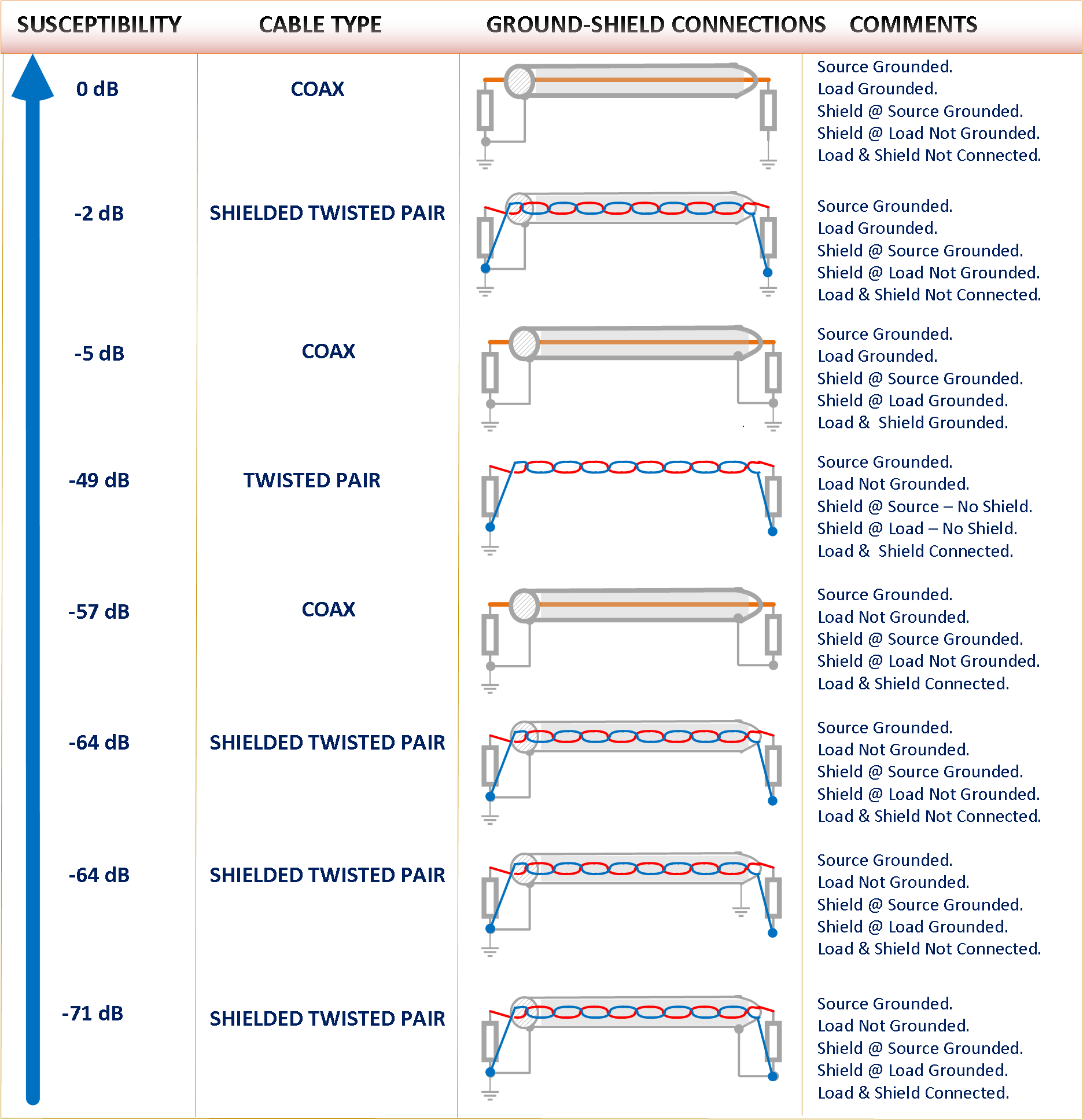
- The shielded twisted pair with both the source and load grounded offers only 2 dB less susceptibility to low-frequency noise. Although the grounding of the shield will reduce electric field emissions, many of the advantages of using twisted pair are lost since the load and source are not balanced (load & source are both single-ended grounded).
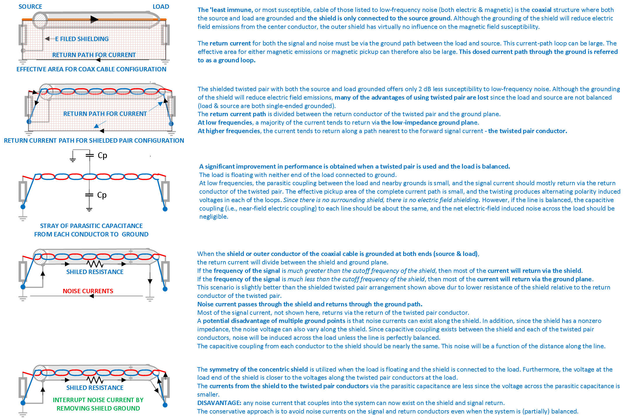
The return current path is divided between the return conductor of the twisted pair and the ground plane.
At low frequencies, a majority of the current tends to return via the low-impedance ground plane. At higher frequencies, the current tends to return along a path nearest to the forward signal current - the twisted pair conductor.
- The 'least immune, or most susceptible, cable of those listed to low-frequency noise (both electric & magnetic) is the coaxial structure where both the source and load are grounded and the shield is only connected to the source ground. Although the grounding of the shield will reduce electric field emissions from the center conductor, the outer shield has virtually no influence on the magnetic field susceptibility.
- The return current for both the signal and noise must be via the ground path between the load and source. This current-path loop can be large. The effective area for either magnetic emissions or magnetic pickup can therefore also be large. This dosed current path through the ground is referred to as a ground loop.
- A significant improvement in performance is obtained when a twisted pair is used and the load is balanced.
The load is floating with neither end of the load connected to ground.
At low frequencies, the parasitic coupling between the load and nearby grounds is small, and the signal current should mostly return via the return conductor of the twisted pair. The effective pickup area of the complete current path is small, and the twisting produces alternating polarity induced voltages in each of the loops. Since there is no surrounding shield, there is no electric field shielding. However, if the line is balanced, the capacitive coupling (i.e., near-field electric coupling) to each line should be about the same, and the net electric-field induced noise across the load should be negligible.
- When the shield or outer conductor of the coaxial cable is grounded at both ends (source & load), the return current will divide between the shield and ground plane. If the frequency of the signal is much greater than the cutoff frequency of the shield, then most of the current will return via the shield. If the frequency of the signal is much less than the cutoff frequency of the shield, then most of the current will return via the ground plane. This scenario is slightly better than the shielded twisted pair arrangement shown above dur to lower resistance of the shield relative to the return conductor of the twisted pair. Noise current passes through the shield and returns through the ground path. Most of the signal current, not shown here, returns via the return of the twisted pair conductor. A potential disadvantage of multiple ground points is that noise currents can exist along the shield. In addition, since the shield has a nonzero impedance, the noise voltage can also vary along the shield. Since capacitive coupling exists between the shield and each of the twisted pair conductors, noise will be induced across the load unless the line is perfectly balanced. The capacitive coupling from each conductor to the shield should be nearly the same. This noise will be a function of the distance along the line.
- The symmetry of the concentric shield is utilized when the load is floating and the shield is connected to the load. Furthermore, the voltage at the load end of the shield is closer to the voltages along the twisted pair conductors at the load. The currents from the shield to the twisted pair conductors via the parasitic capacitance are less since the voltage across the parasitic capacitance is smaller. DISAVANTAGE: any noise current that couples into the system can now exist on the shield and signal return. The conservative approach is to avoid noise currents on the signal and return conductors even when the system is (partially) balanced.
Christian Rosu, Nov 18, 2021.