Differential-mode RF emissions in a CISPR 25 component level configuration occur due to the flow of current (IDM) via signal paths in which the forward and return conductors are not routed together, thereby forming a conductor loop. The resulting magnetic field from the conductor loop is proportional to the current IDM, the area of the loop and the square of the frequency of the RFI current.
Common-mode RF emissions occur due to undesired parasitic effects, e.g. due to inductances in the current return path or unsymmetries during signal transmission. If we connect a cable to a DUT of it may function like an antenna allowing a common-mode current ICM to flow. Both signal and power supply lines can function as efficient antennas. Here, our rule of thumb is that line lengths that do not exceed λ/10 are uncritical, whereas longer lines (e.g. λ/6) must be treated as potential sources of RF emissions.
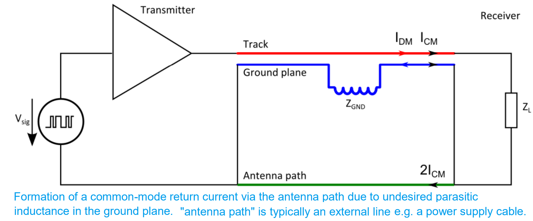
The magnitude of the voltage drop on the ground plane and thus the magnitude of the common-mode current coupled into the connected line are determined by the parasitic inductance and the slope steepness of the signal.
We cannot assume that differential mode radiated emissions are not dominant nor an infinite ground plane. A ground plane with finite width has inductance.
Common-mode RF emissions can also occur due to differential mode signal transmission.
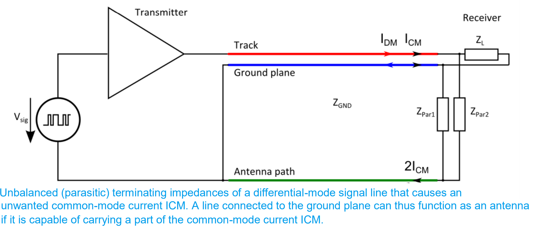
If the parasitic terminating impedances of a differential mode transmission path differ substantially, in addition to the desired differential-mode current IDM a common-mode current ICM will also flow via the ground plane that connects the transmitter and receiver modules. This unwanted ground current ICM can then also be coupled into lines connected to DUT and cause emissions in the far field.
The strength of the common mode current and the level of radiated emissions depend on the inductance of the ground plane. The value of this inductance depends on the structure of the transmission line.
The ground plane inductance in a symmetric structure is:
L21 = (µ0/2π) * ln((tπ/W)+1)
Where:
W is the width of the ground plane
t is the height of the harness
The ratio of the height of the harness and the width of the ground plane determines the GP inductance.
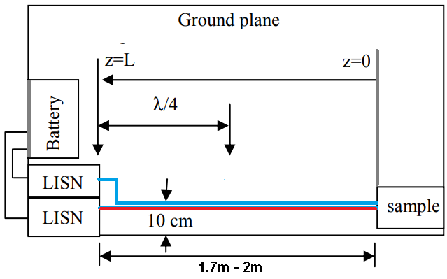
As the harness is closer to the edge of the ground plane, the measurement tolerances are higher since the ground plane inductance increases. The tolerances in RE measurments are acceptable when the distance of the harness to the ground plane edge is 10 cm.
Since common mode radiated emissions occur through the ground plane (or the whole setup), the length of the ground plane can impact the tolerances in RE measurments. Longer the ground plane, higher the radiated emissions level.
Christian Rosu, 2022-03-07