20. July 2015 11:29 by Christian in
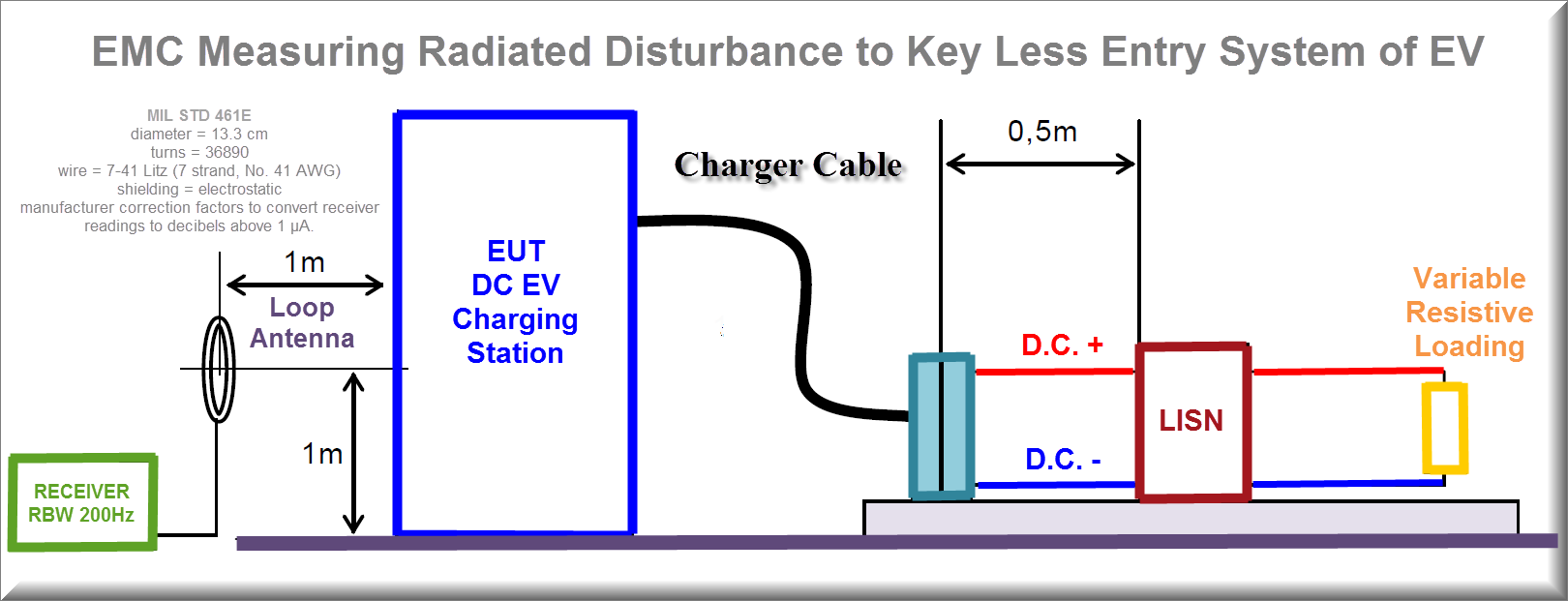
This test simulates the effects of the radiated magnetic fields on a keyless entry system due to close proximity to other vehicles charging systems. The charging equipment is connected to a resistive load that represents 100 % of the load of maximum.
1. Turn on the charging equipment and allow sufficient time for stabilization.
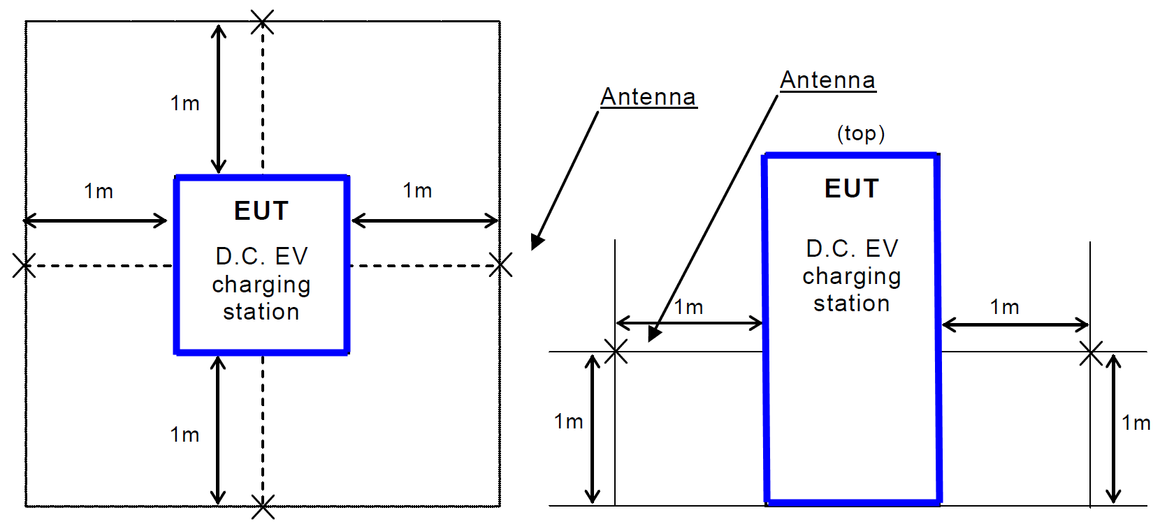
2. Locate the loop sensor 1 m from the charging equipment face or electrical interface connector being probed. Orient the plane of the loop sensor parallel to the charging equipment faces and parallel to the axis of connectors.
3. Scan the measurement receiver over the applicable frequency range to locate the frequencies of maximum radiation, using the bandwidths and minimum measurement times according to MIL STD 461 or CISPR 16-2-3.
4. Tune the measurement receiver to one of the frequencies or band of frequencies identified in step 3 above.
5. Monitor the output of the measurement receiver while moving the loop sensor (maintaining the 1 m spacing) over the face of the EUT or around the connector. Note the point of maximum radiation for each frequency identified in step 4.
6. At the point of maximum radiation, orient the loop sensor in the vertical plane to give a maximum reading on the measurement receiver and record the reading.
7. Repeat step 4 through step 6 for at least two frequencies of maximum radiation per octave of frequencies below 200 Hz and for at least three frequencies of maximum radiation per octave above 200 Hz.
8. Repeat step 2 through step 7 for each face of the EUT and for each EUT electrical connector.


Sources: MIL STD 461 or CISPR 16-2-3