EMC FLEX BLOG A site dedicated to Automotive EMC Testing for Electronic Modules

Test Procedure vs Test Method in automotive electronics EMC testing

11. December 2020 13:13 by Administrator in EMC/EMI, OEM Specs, Standards, Test Methods
Differences between Test Procedures and Test Methods in automotive EMC/EMI vocabulary.

Test Procedure:

  • what the activity is (DUT type)
  • who is to perform the activity (EMC Testing Laboratory)
  • when the activity is to take place

This is more of an EMC Test Plan Template document that:

  • defines the DUT classification and category
  • lists required EMC Test Methods defined by the automotive OEM specs or International Standards (ISO, CISPR, SAE, etc.).


Test Method:

  • how  the actual EMC testing is to be carried out (test equipment configuration)
  • defines measurable data format for reporting and acceptable stress level limits 

This more of a Work Instruction outlined by automotive OEM EMC specs and international standards.

Christian Rosu, Dec 11, 2020.

DUT configuration for CISPR 25 ALSE chamber ambient

28. October 2020 07:03 by Christian in EMC/EMI, EMC TEST PLAN, OEM Specs, Standards, Test Methods
The automotive OEM specs do not specify how to configure the DUT during CISPR 25 chamber ambient measurements.

The automotive OEM specs do not specify how to configure the DUT during CISPR 25 chamber ambient measurements. DUT must be unpowered, all other DUT support equipment must be powered and as much as possible functional to correctly evaluate RF emissions noise floor before start testing. This leaves at least three scenarios for how to configure the DUT.

 
1) Disconnect the DUT from test harness. 
  1.  Test harness connectors are removed from
  2.  DUT is unpowered.
  3.  The 1.7 m test harness is unterminated on DUT side, no potential ground loops with Load Simulator.
  4.  The 5uH LISN remains present.
  5.  The Load Simulator and all support equipment remains powered.
 
2) Disconnect DUT's B+ line from LISN output.
  1.  Test harness connectors are plugged into DUT.
  2.  DUT is unpowered by disconnecting B+ line LISN input from Battery.
  3.  The 1.7 m test harness terminated on both ends, therefore potential ground loops with Load Simulator are possible.
  4.  The 5uH LISN remains present.
  5.  The Load Simulator and all support equipment remains powered.
 
3) Diconnect DUT's B+ line from LISN output.
  1.  Test harness connectors are plugged into DUT.
  2.  DUT is unpowered by disconnecting DUT B+ line from LISN output.
  3.  The 1.7 m test harness terminated on both ends, therefore potential ground loops with Load Simulator are possible.
  4.  The 5uH LISN is not present anymore, and this somehow violates CISPR 25 requirement.
  5.  The Load Simulator and all support equipment remains powered.
 
Christian Rosu

Automotive EMC Load Simulators

28. September 2020 11:20 by Christian in EMC/EMI, EMC TEST PLAN, Load Simulator
During EMC compliance validations we monitor DUT (Device Under Test) errors visible for the occupant

The Load Simulator is defined in ISO 11452-1:2015 as: “physical device including real and/or simulated peripheral loads which are necessary to ensure DUT nominal and/or representative operation mode.”


During EMC compliance validations we monitor DUT (Device Under Test) errors visible for the occupant in vehicle in parallel with stored or not stored yet DTC (Diagnostic Trouble Codes). Disruptions in data bus or communication bus that do not set a DTC are not visible for the end user, since many of them are controlled safely by Vehicle Software & BCM.


 The driver can be distracted by vehicle cluster signs/indicators turning red, like an imminent hazard. 

  • If the incident self-recovers, it may not be a problem but it depends on DUT's Classification and Required Immunity Level.
  • If the DUT does not self-recover and require driver's intervention, then the LS support software must mimic the user response to resume operation (automation). Such anomaly is marked in a data log but should not be a reason to stop on-going testing.
  • If the DUT does not self-recover requiring Hard Reset (VBATT on-off-on), then it's really bad. This is like a stop show but make sure it is always driven by DUT, never the LS.
  • The pass/fail criteria mentioned in EMC test plan must guide your LS design effort, especially to decide on what type of FO monitoring equipment is needed.
  • Ideally is to use production intent DUT's I/O loading and Vehicle Software reducing the entire effort to monitoring the communication bus & FO equipment (e.g. FO Voltage Probes, FO Signal/Data Probe).
  • The moment you’re forced to use excessive HW/SW simulation, you practically spend more time validating the Load Simulator instead of focusing on DUT's EMC performance.
  • If possible, avoid using active electronic components for the LS placed inside ALSE chamber.
  • Use production intent loads, ideally EMC validated by OEM.
  • Use FO devices that are certified for 200 V/m, CISPR 25, 30KV ESD.
  • The support software should not stop the show if errors occur, only the DUT should be able to stop the show.
  • Pay attention how is the shielding of I/O lines terminated/grounded in vehicle and use if possible production intent cables and proper wire gauge.
  • For remote grounded module, make sure the only possible connection to battery negative pole is via supply return line. 
  • The LS metallic enclosure is bonded to GP (ground plane) being used as shield. 
  • The LS metallic enclosure is not being used as grounding point for DUT or LS electronics.
  • All signal return lines are closed to their source, never to GP.


Grounding Requirements

If DUT and LS grounding requirements are not defined by the automotive OEM EMC spec or Test Plan, then using automotive industry standards is acceptable (ISO 11452-2:2004-11-01, ISO 11452-4:2011-12-15, ISO 7637-2:2011-03-01, CISPR 25:2016-10-27):

"The DUT shall be placed on a non-conductive, low relative permittivity (dielectric-constant) material (εr ≤ 1,4), at (50 ± 5) mm above the ground plane. The case of the DUT shall not be grounded to the ground plane unless it is intended to simulate the actual vehicle configuration.”  


Preferably, the load simulator shall be placed directly on the ground plane. If the load simulator has a metallic case, this case shall be bonded to the ground plane. Alternatively, the load simulator may be located adjacent to the ground plane (with the case of the load simulator bonded to the ground plane) or outside of the test chamber, provided the test harness from the DUT passes through an RF boundary bonded to the ground plane.” 


“Bonded – grounded connection providing the lowest possible impedance (resistance and inductance) connection between two metallic parts with a d.c. resistance which shall not exceed 2,5 mΩ. Note 1 to entry: A low current (≤100 mA) 4-wire milliohm metre is recommended for this measurement" . This resistance needs to be verified with a milliohm meter. (ISO 11452-1:2015-06-01, MIL-STD-461G:2015-12-11).


Grounding Solutions:

  • Copper Tape (colored) with conductive adhesive.
  • Silver Tape with pressure sensitive adhesive (better contact), and tin-plating allowing soldering the tape directly to the ground plane, overall better resistance to corrosion.
  • Bonding Strap made from a semi-rigid flat metallic braid/weave that is copper tinned/untinned. Bonding straps are better than wires since their length to width ratio has lower inductance per unit length. The EMC test plan ahould specify that any ground straps used maintain a “5:1 length to width ratio or less” per MIL-STD-464C:2010-12-01. The impedance of ground straps at high frequencies varies with their width, length and addition of connectors (e.g. banana plugs). Since the ends of the braid may fray, ideally is to solder the ends of the braid. If adding a hole for a fastener (e.g. screw), the edges of the hole should be soldered to prevent fraying. The best grounding solution is to solder the braid to the ground plane.

Before using any of the above grounding solutions, the ground plane should be cleaned from oxidazation to achive better conductivity.


Grounding Point:

The EMC Test Plan should specify the DUT's case grounding point to ensure repeatsble results. The same for Load Simulator. 


Christian Rosu, Sep 28, 2020.


Validation Testing for Compliance to Automotive EMC Specs/Standards - EMC Test Plan

29. March 2020 05:35 by Christian in EMC/EMI, Load Simulator
A successful electronic module validation testing depends on:DUT Design Performance (60%).Load Simul

A successful electronic module validation testing depends on:


  1. DUT Design Performance (60%).
  2. Load Simulator & Support Equipment EMC compliance (20%). 
  3. EMC Test Plan (20%).

The Load Simulator must be CISPR-25, ISO 11452-2, and ISO 11452-4 compliant.

EMC Test Plan:

  • Select representative samples covering multiple vehicle platforms having design differences.
  • Select all applicable test methods except those that:
    • are not required for certain module category as outlined by OEM spec selection matrix.
    • are in conflict with design requirements imposed by Component Technical Specification (CTS).
  • Define for each DUT Type/Model:
    • Known sources of RF noise.
    • Functions Performance Classification.
    • Operating Modes per Test Method:
      • DUT Configuration:
        • Block Diagram including grounding scheme.
        • Connectors Pinout.
        • Test Harness Type & Mate Connectors:
          • standard 1.7 to maximum 2 m.
          • customized (inserted banana jacks & plugs @ 20cm from DUT  connectors).
          • ESD mate connectors with 2.5 solid core wire.
      • Activation Method:
        • Load Simulator HW/SW Configuration - Operating Manual.
        • Other DUT Support Equipment (e.g pneumatic activation).
        • Other DUT Support Software.
      • Monitoring Method:
        • DUT Test Points.
        • Load Simulator Test Points.
        • LS Configuration (e.g. switches, I/O lines). More details in LS Operating Manual.
      • How to evaluate a HW/SW Reset condition.
      • How to evaluate successful Self-Recovery.
      • Measurable Parameters & Tolerances:
        • Support Equipment:
          • Resolution (e.g. use oscilloscope vs DMM during voltage transients/dips/drops).
          • Fiber Optic (CAN, USB, E-Net, LVDS, etc). Must be 200 V/m compliant.
        • Support Software:
          • Configuration, data files format.
      • Differences between DUT Reset and Support Equipment Reset.
      • Pass/Fail Criteria per Test Point and DUT Function.
    • Reporting Data type and format (e.g. tables, plots, pics).
  • Negotiate EMC compliance deviations based on known DUT design limitations driven by cost/delivery.


Calibrating Filed Probes for Automotive EMC Standards

24. February 2020 09:31 by Christian in EMC/EMI, Test Methods, Calibrations, Uncertainty
IEEE 1309:2013 is the Standard for Calibration of Electromagnetic Field Sensors and Probes (Excludin

The accuracy of RF Field Level during ALSE RF Immunity per ISO 11452-2:2019 Substitution Method relies on the Field Probe calibration factors. An incorrect Field Probe Calibration may result in significant deviations from the field levels called by automotive OEM specs. The Field Probe Calibration Report provides correction factors that are introduced into RF Immunity Test Software (e.g. TILE, NEXIO). Using calibration factors acquired at 15 V/m instead of 300 V/m can force the RF Amplifier output to maximum w/o the Field Probe to report expected Field Level. Moving transmitting antenna 10 inches closer to the Field Probe would allow the probe to report the expected field level, however this level is in fact higher as consequence of using bad correction factors.

RF Field Probe Selection for EMC Testing

Calibration Factors: corrections are provided as dB adjustments & multiplication factors. Maximum field measurement accuracy is achieved when the detailed 3-axis calibration is applied.

     Probe Calibration Certificate

     A) filed level applied via calibration antenna (V/m)

     B) filed level reported by probe (V/m)

     C) calculated multiplier factor

          A = B * C (e.g. 100 V/m = 120 V/m x 0.8333 where 0.8333 is the correction factor)

Sensitivity/Dynamic Range: e.g. (0.5 – 800V/m for 0.5 MHz – 6 GHz)

Linearity: the measure of deviation from an ideal response over the dynamic range of the probe that may vary as a function of the applied field level. (e.g. ±0.5dB 0.5 – 800 V/m).

Overload: the field level where damage can occur to the probe (e.g. 1000 V/m CW).

Isotropic Deviation: the variation of the probe’s response from ideal as it is rotated in the field. The minimal isotropic deviation of spherical probes (±0.5dB 0.5 MHz – 2 GHz).

Response time: the time a probe takes to respond to an applied RF field (e.g. 20 ms).

Sample rate: the rate at which information can be retrieved from the probe (e.g. 50 samples/second). 

Probe Type: refers to the configuration of the probe sensors. 


  • An isotropic RF filed measures the total value of the field level and is unaffected by field polarity. This is accomplished by summing measurements from three different sensors placed orthogonal to each other. 
  • Non-isotropic probes measure fields in one polarity at a time for electric field or magnetic field. 


IEEE 1309:2013 is the Standard for Calibration of Electromagnetic Field Sensors and Probes (Excluding Antennas) from 9 kHz to 40 GHz. 

The EMC lab must inform the calibrator about critical requirements imposed by automotive specs/standards for proper field calibration factors:


  1. The frequency range or center frequencies as delineated by automotive OEM EMC specs (e.g CS.00054, GMW3097, FMC1278).
  2. The filed level for each frequency band (e.g. 80V/m, 100V/m, 200V/m, 300V/m)
  3. Field Probe orientation (all three axes X, Y, Z facing antenna).
  4. Use 1 meter antenna distance to Field Probe. This is not always possible, therefore using a lower distance in far field  (e.g. 30 cm) should be acceptable.
  5. Calibrate the probe using CW with transmitting antenna in both horizontal/vertical polarization.


IEEE 1309:2013 A.2.4.3 Field strength: if the probe or sensor linearity is better than ± 0.5 dB, the frequency response calibration of the probe can be performed at any field strength level, but preferably close to the field levels used in the EUT tests. It is also required that the same probe range and/or gain settings as used in the EUT tests are used in the probe calibrations.

IEEE 1309:2013 A.2.4.4 Linearity check for probe or sensor:

For applications needing multiple field strength calibrations, e.g., 3 V/m, 10 V/m, and 18 V/m, the linearity tests shall be performed for each level. Note that for automotive EMC testing the above e.g. translates to levels like 100V/m, 200V/m, 300V/m.

IEEE 1309:2013 A.2.4.5 Probe isotropic response

For isotropic probes using three orthogonal elements, it is recommended that the frequency response and linearity response measurements be performed for each axis individually. Each axis should be aligned with the incident field successively to provide a maximum response. Probe calibration in a single orientation, such as only the orientation used in a UFA calibration, is not recommended, because the transmitting antennas, separation distances, and the end-use environment are typically not the same between the two setups.

Example of RI ALSE Test Configuration
 
 
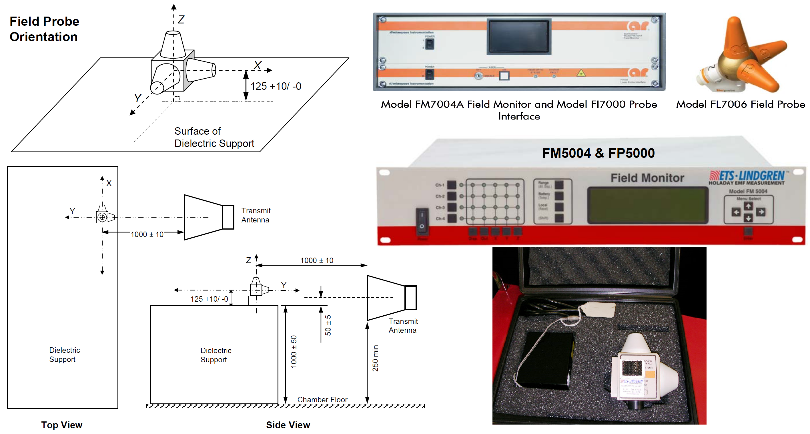
Example of Field Calibration using Field Probe Type A per FMC1278R3 
 
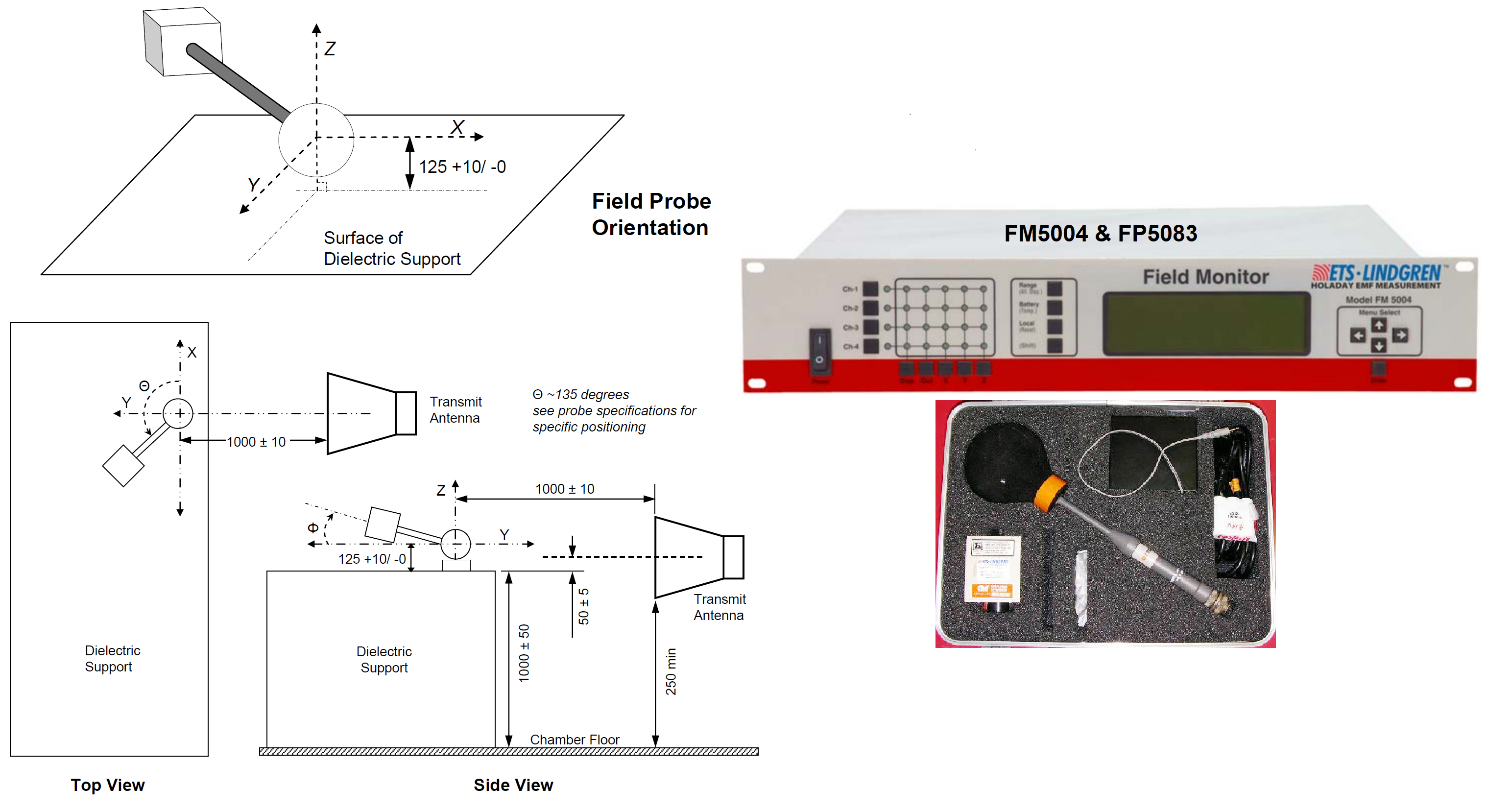
Example of Field Calibration using Field Probe Type B per FMC1278R3 


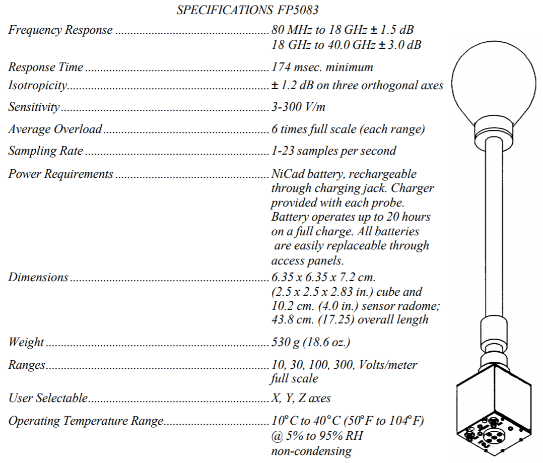
Example of Field Probe Specs (AR FP5082)


References: IEEE 1309:2013, ISO 11452-2, FMC1278 Rev3, 28401NDS02 [8], AR App Note #44
Christian Rosu, Feb 24, 2020
 

AR_App_Note_44_RF_Field_Probe_Selection.pdf (352.8KB)

Rhode & Schwarz Equipment Calibration Interval:

https://gloris.rohde-schwarz.com/anonymous/en/pages/toplevel/calibration-process.html